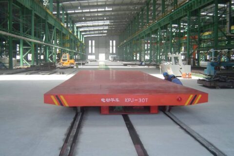
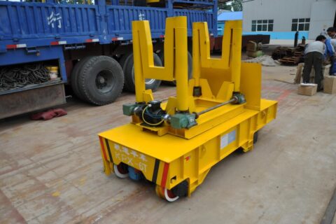
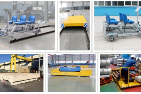
KPC Series Enclosed Conductor Rail Flat Car for Steel Coil Transport
Enclosed Conductor Rail Electric Flat Car
Model: KPC Series; Rated Load Capacity: 6-300 tons; Power Supply: Enclosed Conductor Rail (three-phase 380V); Travel Speed: 15-30 m/min (adjustable); Track Gauge: Standard 1435mm (customizable from 762 to 2000mm). The KPC series conductor rail flat car is one of Kelude Heavy Industry's core self-developed products, specifically designed for heavy-duty, long-distance, and continuous industrial transport applications. Its enclosed conductor rail power supply eliminates the charging downtime associated with battery-powered flat cars and the travel distance limitations of cable-reel units. Widely used in steel plants, metallurgy, shipbuilding, heavy machinery manufacturing, and other industries, the KPC series is the ideal solution for efficient heavy material handling within workshops.
The conductor rail can be installed in a trench, on the floor surface, or overhead, offering flexible installation options that adapt to any factory layout. When paired with a flip-type cover plate mechanism, it allows other floor-level vehicles to pass without obstruction, making it one of the most economical and proven power supply solutions for electric flat cars.
Product Introduction
The KPC series electric flat car is powered via an enclosed conductor rail system. Its operating principle involves a trench dug alongside the crane rail, within which the enclosed conductor rail is installed. The trench is covered by steel plates hinged on one side to the floor. As the flat car moves, a trench flip mechanism mounted on the car lifts the cover plates. This mechanism houses the cables connected to the conductor rail's current collector relay. After the car passes, the cover plates automatically return to their original position, ensuring seamless passage for other wheeled vehicles. This trench-type conductor rail system imposes no restrictions on travel distance, does not compromise the car's travel speed, and offers smooth operation, high reliability, and a low failure rate, making it the preferred choice for heavy-duty, long-distance transport applications. Alternatively, the enclosed conductor rail can be mounted directly on the floor surface or overhead (where it does not interfere with other transport modes), which simplifies installation and reduces costs. Among all power supply methods for electric flat cars, this is the most rational and economical conductive solution.
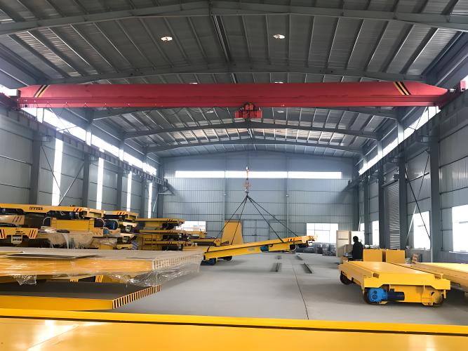
Product Images
Product Features
- Unlimited Travel Distance: The enclosed conductor rail power supply is not limited by travel distance, making it ideal for long-distance material transport without the need for frequent charging or battery replacement.
- Stable and Reliable Operation: The trench flip mechanism automatically lifts and resets the cover plates without affecting the passage of other vehicles, ensuring a low failure rate and minimal maintenance.
- Heavy-Duty Load Capacity: Rated load capacity ranges from 6 to 300 tons, with larger capacities available upon request to meet demanding heavy industrial requirements.
- Flexible Installation: The conductor rail can be installed in a trench, on the floor, or overhead, adapting to various factory layouts while optimizing cost.
- Adjustable Travel Speed: Standard speed is 15-30 m/min, adjustable to suit specific operating conditions, and can be integrated with automated control systems for precise start/stop positioning.
Working Principle
The KPC series conductor rail flat car draws three-phase 380V power from the enclosed conductor rail installed in a trench beside the track. The car is equipped with a trench flip mechanism that lifts the cover plates as it travels, allowing the internal carbon brush current collector to make contact with the conductor rail and supply power to the drive motor, which propels the wheels. Once the car has passed, the cover plates automatically reset, keeping the floor level and clear for other vehicles.
The key advantage of this power supply method lies in the sliding contact between the carbon brush collector and the conductor rail — there is no cable drag loss, and travel distance is virtually unlimited: the rail simply extends as far as the car needs to run.
Structural Composition
The KPC series electric flat car consists of the following core structural components:
Frame: Fabricated from Q235B (≈S235JR) high-quality carbon structural steel plates, the frame undergoes full annealing to relieve welding-induced internal stresses, ensuring long-term load-bearing performance without deformation. Depending on the load capacity, the main girder features either a box or I-beam cross-section, with load-bearing capacity optimized through finite element analysis.
Drive System: Comprises an electric motor and gearbox. The motor is a three-phase asynchronous motor (380V/50Hz) with power ratings ranging from 2.2kW to 15kW×2. The gearbox utilizes worm gear or hardened tooth flank gearing for high transmission efficiency and low noise. Heavy-duty models (150t and above) are equipped with a dual motor, dual-drive configuration for smooth starting and strong climbing capability.
Wheel Assembly: Features cast steel wheels with tread surfaces hardened by medium-frequency induction quenching (hardness HRC45-50) for extended wear life. Wheel bearings use Spherical Roller Bearings that automatically compensate for installation misalignment. Depending on track gauge and load capacity, 4 to 8 wheels are configured (with auxiliary wheels added on heavy-duty models).
Electrical Control System: Includes a control box (with built-in Circuit Breaker, Contactor, Thermal Overload Relay), Travel Switch / Proximity Switch, and remote control receiver module. The control box has an IP54 Protection rating and provides Overload Protection, Short-Circuit Protection, and Emergency Stop functionality.
Conductor Rail Power Collection Unit: Consists of a carbon brush Current Collector, flip mechanism, and cables. The carbon brush slides along the conductor rail to collect power, while the flip mechanism automatically lifts and resets the trench cover plates for uninterrupted power supply. The conductor rail has an IP54 Protection rating, suitable for both indoor and outdoor environments.
Application Scenarios
- Steel Plants / Metallurgy Workshops: Cross-workshop transfer of heavy materials such as steel coil, steel plate, and steel billet, typically involving heavy loads and long-travel distances.
- Heavy Machinery Manufacturing: In-workshop movement and assembly station positioning of large equipment components (e.g., wind power tower sections, pressure vessel shells).
- Shipyards / Ports: Horizontal movement of sections and modules, working in tandem with cranes for efficient material flow.
- Railway / Rolling Stock Maintenance: Conveyance of heavy components such as locomotive bogies and wheel sets along maintenance lines.
- Warehouses / Storage Yards: Long-distance horizontal transport of heavy finished or semi-finished goods, replacing forklifts to reduce operating costs.
Technical ParametersNuclear Environment Crane Design
### 10.1 Nuclear Environment Classification and Requirements
Cranes used in nuclear power plants are classified into three categories based on their location:
| Class | Area | Radiation Dose Rate | Seismic Requirement | Ambient Temperature | Typical Equipment |
|------|------|-----------|---------|---------|---------|
| Class 1 (Nuclear) | Inside Reactor Building (RPV) | >1Sv/h | SSE (Safe Shutdown Earthquake) | 40~150℃ | Polar Crane, Fuel Loading Machine |
| Class 2 (Nuclear) | Inside Containment | 0.1~1Sv/h | OBE+SSE | 30~60℃ | Fuel Transfer Device |
| Class 3 (Nuclear) | Auxiliary Building | <0.1Sv/h | OBE | 20~40℃ | Equipment Maintenance Crane |
### 10.2 Radiation-Proof Sealing Design
**Material Selection**:
- Electronic components: CMOS/SOS (sapphire substrate) radiation-hardened process, total dose ≥100krad
- Cables: Radiation-resistant cross-linked polyethylene (XLPE), ≥100Mrad
- Seals: EPDM (ethylene propylene diene monomer), radiation resistance ≥50Mrad
- Lubricating grease: Radiation-stable silicone-based grease
- Optical lenses: Quartz glass + lead glass protective cover
**Sealing Structure**:
1. Dual O-ring seal + helium leak test (leak rate ≤10⁻⁹ Pa·m³/s)
2. Penetrations use metallic seals (welding + flange double seal)
3. Control box nitrogen positive pressure protection (pressure 50~100Pa)
4. All surfaces coated with easy-decontamination coating (stainless steel + Teflon)
### 10.3 Seismic Design
Seismic design of nuclear-grade overhead cranes follows the RG 1.60 standard response spectrum:
**Analysis Methods**:
- Response Spectrum Method (RSM): Multi-modal superposition, considering the first 10 modes
- Time History Analysis: Input three-directional artificial seismic waves (T=20s, Δt=0.01s)
- Equivalent Static Method: Used for preliminary design, amplification factor 3~5
**Seismic Measures**:
- Anti-derailment device: Double flanges + rail clamp + L-shaped anti-derailment block
- Anti-overturning: Increase wheelbase/span ratio (≥1/4)
- Shear resistance: Connection bolt grade ≥10.9
- Equipment fixing: All non-structural components withstand acceleration ≥5g
### 10.4 Special Safety Systems
| Safety Function | Implementation Method | SIL Level |
|---------|---------|--------|
| Core anti-drop protection | Dual redundant mechanical brake + electronic speed limiter | SIL3 |
| Anti-collision with reactor internals | Laser ranging + mechanical limit + software limit | SIL2 |
| Load non-release | Electromagnet + mechanical lock dual safety | SIL3 |
| Automatic shutdown on earthquake | Seismometer + acceleration switch (triggered at 0.2g) | SIL2 |
---
## Nuclear Environment Crane Design and Certification
### 18.1 Safety Classification of Nuclear Power Cranes
| Safety Class | Definition | Seismic Category | Quality Assurance Grade | Design Life | Typical Equipment |
|:-------:|:----|:-------:|:-------:|:-------:|---------|
| SC-1 | Safety-critical | Class I (SSE+OBE) | QA1 | 60 years | Reactor Building Polar Crane |
| SC-2 | Safety-related | Class I (SSE) | QA2 | 60 years | Fuel Handling Crane |
| SC-3 | Safety-influencing | Class II (OBE) | QA3 | 40 years | Auxiliary Building Crane |
| NC (Non-Safety) | No safety impact | Class II | QA4 (Commercial Grade) | 30 years | Conventional Island Crane |
### 18.2 Seismic Design Parameters
**Seismic Load Combinations**:
| Load Case | Load Composition | Allowable Stress Amplification Factor | Allowable Deformation |
|:----:|---------|:-------------:|:-------:|
| OBE (Operating Basis Earthquake) | D+L+SSE(0.5OBE)+W | 1.33 (short-term) | 1/200 × Span |
| SSE (Safe Shutdown Earthquake) | D+L+SSE(1.0SSE) | 1.50 (accident) | 1/100 × Span |
| SSE+SL-2 (Ultimate) | D+0.25L+SSE | 1.70 (extreme accident) | Maintain integrity without collapse |
> D = Dead Load, L = Live Load, SSE = Safe Shutdown Earthquake, W = Wind Load
**Seismic Response Analysis Parameters for Nuclear-Grade Overhead Cranes**:
| Parameter | SC-1 Class | SC-2 Class | SC-3 Class |
|:----|:-----:|:-----:|:-----:|
| Design Peak Ground Acceleration PGA (g) | 0.30 | 0.25 | 0.20 |
| Damping Ratio (SSE) | 2% (welded) / 4% (bolted) | 3% (welded) / 5% (bolted) | 4% (welded) / 6% (bolted) |
| High-Frequency Cut-off Frequency (Hz) | 50 | 33 | 33 |
| Number of Modes Required | ≥20 modes | ≥12 modes | ≥10 modes |
| Response Spectrum Amplification Factor | 2.5 | 2.5 | 2.0 |
| Seismic + Wind Load Combination | Not required simultaneously | Not required | Not required |
| Functional Verification | Operable after earthquake | Requires inspection after earthquake | Requires inspection after earthquake |
### 18.3 Radiation-Proof Sealing Design
| Sealing Location | Material | Sealing Class | Radiation Tolerance (MGy) | Decontamination Factor (D.F.) |
|:-------:|:----:|:-------:|:----------:|:----------:|
| Main Girder Interior | Epoxy sealant | Airtight (10⁻³Pa·m³/s) | 10 | 10² |
| Motor Junction Box | Fluororubber O-ring | IP67 | 5 | 10³ |
| Limit Switch | Metal seal + silicone | Watertight | 3 | 10² |
---
## Nuclear-Grade Overhead Crane Maintenance Procedures
### 21.1 Replacement Intervals for Nuclear-Grade Components
| Component | Design Life | Mandatory Replacement Interval | Inspection Interval | Tracking Method |
|:-------:|:-------:|:----------:|:-------:|---------|
| Main Hoist Wire Rope | 5 years | 5 years | Monthly | Magnetic flux testing + visual inspection |
| Auxiliary Hoist Wire Rope | 8 years | 8 years | Quarterly | Visual inspection + diameter measurement |
| Brake Lining | 2 years | 2 years | Monthly | Thickness measurement |
| Brake Wheel | 10 years | 10 years | Annually | Hardness + runout check |
| Hoist Motor Bearing | 5 years | 5 years | Quarterly | Vibration monitoring |
| Trolley Motor Bearing | 8 years | 8 years | Semi-annually | Vibration monitoring |
| Gearbox Oil Seal | 3 years | 3 years | Annually (during oil change) | Visual inspection |
| Overload Limiter Sensor | 10 years | 10 years | Quarterly | Calibration verification |
| Limit Switch | 5 years | 5 years | Monthly | Operational test |
| Safety PLC (Complete Set) | 15 years | 15 years | Annually | Functional test |
| Brake Spring | 5 years | 5 years | Annually | Stiffness test |
| Wheel Assembly | 10 years | Based on wear | Quarterly | Diameter + flange thickness measurement |
### 21.2 Pre-Start Inspection Checklist for Nuclear-Grade Overhead Cranes
| No. | Inspection Item | Action | Verdict | Sign-off |
|:---:|:------|:----|:---:|:---:|
| 1 | Radiation area access | Confirm radiation monitor readings are within safe range | □Pass □Fail | |
| 2 | Control power supply | Switch on control power, confirm instrument self-check is normal | □Normal □Abnormal | |
| 3 | Brake status | Visually confirm all 4 brakes are in braking position | □Engaged □Not Engaged | |
| 4 | Limit switches | Manually trigger upper/lower limits, confirm correct operation | □Normal □Abnormal | |
| 5 | Overload limiter | No-load display reads 0.0±0.1t | □Normal □Abnormal | |
| 6 | Emergency Stop button | Press Emergency Stop, confirm main power is cut off | □Normal □Abnormal | |
| 7 | Safety door interlock | Open safety door, confirm automatic power cut-off | □Normal □Abnormal | |
| 8 | Wire rope reeving | Visually confirm wire rope is seated in pulley grooves, no jumping or dislodging | □Normal □Abnormal | |
| 9 | Lubrication condition | Oil levels at all lubrication points are normal | □Normal □Abnormal | |
| 10 | Video monitoring | Camera images on the operator console are clear | □Clear □Blurry | |
### 21.3 Emergency Response for Nuclear-Grade Overhead Crane Faults
| Fault Type | Emergency Operation | Follow-up Inspection | Recovery Condition | Recording Requirement |
|---------|---------|---------|---------|---------|
| Brake failure (load drop) | Immediately press Emergency Stop → manually lower brake → alarm | Comprehensive inspection of brake/gearbox | Replace faulty parts + full-load test | Detailed incident report |
---
## Wheel Design
### 6.1 Wheel Material and Hardness
| Duty Class | Recommended Material | Tread Surface Hardness | Flange Hardness | Service Life |
|---------|---------|---------|---------|---------|
| A3-A5 | ZG55 (Cast Steel) | HB 300-350 | HB 280-330 | 3-5 years |
| A6 | ZG50Mn2 (Manganese Steel) | HB 320-380 | HB 300-350 | 5-8 years |
| A7 | ZG50MnMo (Molybdenum Steel) | HB 350-420 | HB 320-380 | 6-10 years |
| A8 | ZG42CrMo (Chromium-Molybdenum Steel) | HB 400-480 | HB 360-420 | 8-12 years |
### 6.2 Wheel Diameter Selection
```yaml
Wheel Diameter Selection Principles:
Wheel diameter D ≥ Tread surface width × 15-25
Tread surface width ≈ Crane rail width - 4-6mm
Reference:
P38 rail (width 68mm) → Tread surface ≈ 64mm → D ≥ 350mm
QU70 rail (width 70mm) → Tread surface ≈ 65mm → D ≥ 400mm
QU80 rail (width 80mm) → Tread surface ≈ 75mm → D ≥ 450mm
QU100 rail (width 100mm) → Tread surface ≈ 95mm → D ≥ 500mm
Common Wheel Diameters:
50t crane recommended: ∅600-700mm (double flange)
32t crane recommended: ∅500-600mm
20t crane recommended: ∅400-500mm
10t crane recommended: ∅350-400mm
Flange Types:
Double flange: Standard for general-purpose cranes
Single flange: For large spans (outer side guiding)
No flange: Rarely used (requires horizontal guide wheels)
```
### 6.3 Wheel Faults and Maintenance
```yaml
Flange Wear:
Causes: Misaligned rail / end carriage deformation / excessive wheel-rail clearance
Measurement: Measure flange thickness with vernier caliper
Criteria: 70% of original thickness → warning, 50% → replacement
Replacement: Press-fit or shrink-fit
Tread Surface Wear / Spalling:
Causes: Improper heat treatment / overload / material defects
Measurement: Measure reduction in tread surface diameter
Criteria: Diameter reduction > 5% of original → replacement
Repair: Build-up welding + machining (limited to 1 time)
Wheel Bearing Damage:
Sound: Periodic low-frequency rumbling noise
Temperature: Bearing housing temperature > 80°C
Causes: Poor lubrication / overload / seal failure
Remedy: Disassemble and inspect, replace bearing, clean and lubricate
Wheel Installation Requirements:
Wheel vertical inclination: ≤L/1000 (L = measured length)
Wheel horizontal inclination: ≤L/1000
Center deviation between two wheels: ≤2mm
Coplanarity of four wheels: ≤3mm
```
---
## Machine Parameter Design
### 4.1 Crane Duty Class and Parameter Comparison
```yaml
GB/T 3811-2024 Duty Class Definitions:
Total Number of Work Cycles:
A3: 3.2×10⁵ cycles
A4: 6.3×10⁵ cycles
A5: 1.25×10⁶ cycles
A6: 2.5×10⁶ cycles
A7: 5×10⁶ cycles
A8: 1×10⁷ cycles
Load Spectrum:
Q1: Light (frequently lifting < 1/3 rated load)
Q2: Medium (frequently lifting 1/3 - 2/3 rated load)
Q3: Heavy (frequently lifting > 2/3 rated load)
```
### 4.2 Recommended Machine Parameter Matching
| Rated Load Capacity | Recommended Span Range | Duty Class | Hoisting Speed | Trolley Travel Speed | Crane Travel Speed | Lifting Height |
|---------|------------|---------|---------|---------|---------|---------|
| 5t | 10-22.5m | A3-A5 | 8-12m/min | 20-30m/min | 20-30m/min | 6-16m |
| 10t | 10-28m | A4-A6 | 7-10m/min | 20-30m/min | 20-30m/min | 6-18m |
| 16/20t | 13-31m | A5-A6 | 6-9m/min | 20-30m/min | 20-25m/min | 6-22m |
| 32t | 16-34m | A5-A7 | 5-8m/min | 20-25m/min | 15-20m/min | 8-24m |
| 50t | 19-37m | A6-A7 | 4-6m/min | 15-25m/min | 15-20m/min | 10-28m |
| 80t | 22-40m | A6-A8 | 3-5m/min | 12-20m/min | 10-15m/min | 10-30m |
| 100t | 25-43m | A7-A8 | 2-4m/min | 10-18m/min | 8-12m/min | 12-32m |
### 4.3 Wheel Load Calculation
```python
# Placeholder for wheel load calculation logic
```
---
## Steel Structure Connections
### 6.1 High-Strength Bolt Connections
**Bolt Grades and Selection:**
| Grade | Material | Heat Treatment | Minimum Tensile Strength | Yield Strength | Application |
|------|------|--------|------------|---------|------|
| **Grade 8.8** | 45#/40Cr | Quenched and tempered | 800MPa | 640MPa | General connections (walkways/railings) |
| **Grade 10.9** | 40Cr/35CrMo | Quenched and tempered | 1000MPa | 900MPa | **Core bolts for main girder connections** |
| **Grade 12.9** | 35CrMo/42CrMo | Quenched and tempered | 1200MPa | 1080MPa | Special heavy-duty applications |
**Slip-Resistant vs. Bearing-Type Connections:**
```yaml
Slip-Resistant Connections (Mandatory for main girder connections):
Load transfer principle: Shear force transferred through friction between plates
Installation: Tension control bolts (spline end shears off after final tightening)
Pretension: Must reach design value
Contact surface: Shot blasting / abrasive blasting (friction coefficient ≥0.45)
Characteristics: Minimal shear deformation, good fatigue resistance
Application: Main girder to end carriage / crane rail to crane girder
Bearing-Type Connections:
Load transfer principle: Bearing between bolt shank and hole wall
Installation: Standard torque wrench
Pretension: No strict requirement
Characteristics: Higher load capacity, but greater deformation
Application: Secondary connections such as walkways/ladders/railings
```
**Pretension and Torque Values (Grade 10.9 Slip-Resistant):**
| Bolt Specification | Pretension P (kN) | Installation Torque (Nm) | Wrench Opening | Application Scenario |
|---------|------------|------------|---------|---------|
| M16 | 100 | 210 | 24mm | Connection plates / walkways |
| M20 | 155 | 410 | 30mm | End carriage connections |
| M22 | 190 | 550 | 34mm | Main girder connections |
| M24 | 225 | 710 | 36mm | Main girder connections (large capacity) |
| M27 | 290 | 1030 | 41mm | Large capacity main girders |
| M30 | 355 | 1400 | 46mm | Extra-large capacity |
**High-Strength Bolt Installation:**
```yaml
Installation Procedure:
1. Connection plate surface preparation: Shot blasting Sa2.5 grade
2. Friction coefficient test: ≥0.45 (factory / on-site verification)
3. Bolt holes: Standard holes (d+1.5mm) / Oversized holes (d+3mm, reamed)
4. Initial tightening: 50% of torque value (in sequence)
5. Final tightening: 100% of torque value (tension control type → spline end shears off)
6. Inspection: Random check 10% with torque wrench within 24 hours
7. Coating: Apply sealant and topcoat after final tightening passes inspection
Tightening Sequence:
Start from the center of the bolt group and work outwards radially
Tighten in 2-3 stages (initial → final)
Quality Acceptance:
Torque value deviation: ±10%
No loosening within 48 hours after final tightening
```
---
## Crane Steel Structure Design and Calculation
### 10.1 Main Girder Cross-Section Design
The box girder is the most common cross-section for overhead cranes. The section height is selected as L/14~L/18 (L = span), web plate thickness is 6~14mm (depending on lifting capacity), and flange plate thickness is 10~30mm (depending on wheel load). The main girder must be equipped with stiffeners (transverse stiffener spacing ≤2h, longitudinal stiffener at mid-height of the web), and end plates at both ends for bolted connection to the end carriage.
### 10.2 Main Girder Strength and Stiffness Verification
**Bending Strength**: σmax = Mmax/Wx ≤ [σ] (Q355B: 295MPa, Q420D: 335MPa)
**Shear Stress**: τmax = Qmax·S/(Ix·tw) ≤ [τ] (typically 0.6[σ])
**Deflection (Stiffness) Check**: fmax ≤ [f] = L/700 (Class A5~A6) / L/1000 (Class A7~A8)
### 10.3 End Carriage Design
The end carriage connects the main girders at both ends and transmits loads from the wheels. The end carriage cross-section is typically box-shaped or I-shaped, and must be checked for bending strength, shear stress, and connection bolt strength. The end carriage is connected to the main girder using high-strength bolts (Grade 10.9, M20~M30), subjected to combined shear and tension. Tighten to the design torque value using a torque wrench (pretension deviation ≤±5%).
### 10.4 Crane Girder Bracket Design
The bracket is the critical node connecting the crane girder to the factory building column. A steel bracket consists of the top flange plate, web plate, and bottom flange plate. Design considerations include determining section dimensions to meet strength and stability requirements, weld calculations based on full penetration groove welds, and fatigue verification based on 2 million stress cycles. The crane girder is fixed to the bracket using clamp plates and bolts. Expansion joints are provided in the crane rail at bracket locations (one joint for spacing ≤1000m). Bracket installation verticality ≤1/1000.
### 10.5 Local Stability Calculation for Main Girder
**Web Plate Local Stability**: When h₀/tw > 80√(235/fy), transverse stiffeners must be provided. When h₀/tw > 160√(235/fy), longitudinal stiffeners must also be provided in addition to transverse stiffeners.
**Transverse Stiffener Spacing**: a ≤ 2h₀ (when σ ≤ [σ]), a ≤ h₀ (when local compressive stress is high). Stiffener outstand width bs ≥ h₀/30 + 40mm, thickness ts ≥ bs/15.
**Flange Plate Local Stability**: b/t ≤ 15√(235/fy) (Q355B limit: 12.5, Q420D limit: 11.5). If the width exceeds the limit, longitudinal stiffeners can be used to divide the flange.
### 10.6 Fatigue Strength Verification of Main Girder
Fatigue verification is required for Class A5~A6 cranes, and strictly mandatory for Class A7~A8 cranes. Fatigue calculation uses the stress range method: Δσ ≤ [Δσ]. Fatigue detail categories: Butt welds ([Δσ]=100MPa for plate thickness t≤10mm, [Δσ]=80MPa for t>10mm), Fillet welds ([Δσ]=50~70MPa), Base metal ([Δσ]=120~140MPa). The number of stress cycles is estimated based on the crane duty class: A5: n=5×10⁵ cycles, A6: n=2×10⁶ cycles, A7: n=5×10⁶ cycles, A8: n=2×10⁷ cycles.
### 10.7 End Carriage Connection Bolt Calculation
The end carriage is connected to the main girder using high-strength slip-resistant bolts. The shear capacity of a single bolt is:
---
## Steel Structure Connection Strength Calculation
### 15.1 High-Strength Bolt Group Calculation
**Bolt Group Subjected to Bending Moment + Shear Force**:
```
Maximum bolt tension:
F_t_max = M × y_max / Σ(y_i²) + N / n
Maximum bolt shear:
F_v_max = V / n
Single bolt strength check:
√[(F_t_max/N_tb)² + (F_v_max/N_vb)²] ≤ 1.0
Where:
M — Bending moment (N·mm)
N — Axial force (N)
V — Shear force (N)
y_max — Distance from the farthest bolt to the neutral axis (mm)
n — Total number of bolts
N_tb — Tensile capacity of a single bolt (N)
N_vb — Shear capacity of a single bolt (N)
```
**End Carriage Connection Bolt Calculation Example (32t/22.5m crane)**:
| Parameter | Value | Unit | Formula |
|:----|:--:|:----|:----|
| End carriage connection bending moment M | 2.85×10⁸ | N·mm | M = F_vert × L/2 |
| Vertical shear force F_v | 2.45×10⁵ | N | F_v = (G_crane+G_load)/2 |
| Bolt group arrangement | 4 columns × 3 rows = 12 bolts | — | M24 (Grade 10.9) |
| Bolt spacing (vertical) | 120 | mm | — |
| Bolt spacing (horizontal) | 100 | mm | — |
| Maximum bolt tension F_t_max | 82,500 | N | M×y_max/Σy² |
| Single bolt tensile capacity N_tb | 176,000 | N | A_eff×f_ub |
| Single bolt shear capacity N_vb | 142,000 | N | n_v×A×f_vb |
| Combined stress ratio | **0.64** | — | √[(82.5/176)²+(20.4/142)²] |
| Verdict | ✅ Safe | — | ≤1.0 |
### 15.2 Bracket Weld Strength Calculation
**Fillet Weld Strength Formula**:
```
τ_combined = √[(τ_⊥)² + (τ_∥)²] ≤ f_fw
Where:
τ_⊥ — Shear stress perpendicular to the weld direction
τ_∥ — Shear stress parallel to the weld direction
f_fw — Fillet weld design strength (160MPa, E43 electrode)
```
**Bracket Welding Parameter Table**:
| Crane Specification | Bracket Plate Thickness (mm) | Weld Size k (mm) | Weld Length (mm) | Vertical Weld Stress (MPa) | Horizontal Weld Stress (MPa) | Combined Stress (MPa) | Safety Factor |
|:-------:|:----------:|:-----------:|:----------:|:--------------:|:--------------:|:----------:|:-------:|
| 10t/16.5m | 16 | 6 | 400 | 32.5 | 12.8 | 34.9 | 4.58 |
| 32t/22.5m | 20 | 8 | 500 | 45.2 | 18.6 | 48.9 | 3.27 |
---
## Electrical Protection and Grounding
### 7.1 Electrical Protection Configuration
| Protection Type | Protection Device | Setting Value | Protected Object | Standard |
|---------|---------|-------|---------|------|
| **Short-Circuit Protection** | Circuit Breaker / MCCB | 1.5-2.5 × rated current | Main circuit / branch circuits | GB/T 14048.2 |
| **Overload Protection** | Thermal Overload Relay / Motor Protection Relay | 1.05-1.2 × rated current | Motor | GB/T 14048.4 |
| **Undervoltage Protection** | Contactor coil (self-locking de-energization) | Releases at <85% Un | All loads | GB/T 14048.4 |
| **Earth Leakage Protection** | Residual Current Device (RCD) | 30-300mA | Personnel / equipment | GB/T 6829 |
| **Phase Loss Protection** | Three-phase voltage monitor | Trips if phase loss < 0.5s | Motor | — |
| **Overvoltage Protection** | Surge Protective Device (SPD) | Uc=385V, Up<1.5kV | Power supply line | GBModel Load Capacity
(t) Gauge
(mm) Table Dimensions
(Length×Width)(mm) Height
(mm) Start Button
(m/min) Power Supply
(v) Power
(kw) Weight
(t) Remarks Recommended
Rail KPC-5-1 5 1435 3600×2000 520 30 380v 2.2 3.1 P24 KPC-5-2 5 762 3000×1500 520 30 380v 2.2 2.8 KPC-10-1 10 1435 3600×2000 520 30 380v 2.2 3.3 KPC-10-2 10 762 3600×1500 520 30 380v 2.2 3.0 KPC-20-1 20 1435 4000×2200 650 30 380v 3.5 4.4 P38 KPC-30-1 30 1435 5000×2200 650 30 380v 3.5 5.0 KPC-50-1 50 1435 5500×2500 700 25 380v 5 7.1 P43 KPC-75-1 75 1435 6000×2500 850 20 380v 7.5 9.8 KPC-100-1 100 1435 6500×2800 900 20 380v 11 12.5 P50 KPC-150-1 150 1435 8000×2800 1100 20 380v 7.5×2 27.8 Dual Drive QU100 KPC-200-1 200 1435 8200×2800 1250 20 380v 11×2 33.9 Dual Drive KPC-300-1 300 1435 12800×2800 1350 15 380v 15×2 51.2 Dual Drive
Why Choose Kelude Heavy Industry
- 17 Years of Industry Expertise: Kelude Heavy Industry specializes in the R&D and manufacturing of electric flat cars. Our KPC series has served 200+ factory, mining, and port projects worldwide.
- Fully Integrated In-House Manufacturing: From frame welding and motor assembly to control system commissioning, every step is quality-controlled in-house, with full traceability of key components.
- Custom Engineering Capabilities: Table dimensions, rail gauge, load capacity, and automation interfaces (PLC / remote control / unmanned operation) can all be tailored to your specific site conditions.
- Comprehensive After-Sales Service: A 24-hour national service hotline, plus on-site installation guidance, operator training, and regular inspections.
Service & Support
Henan Kelude Heavy Industry Co., Ltd. provides full life-cycle support for KPC series enclosed conductor rail electric flat cars: pre-sales solution design (tonnage, rail gauge, and power supply recommendations based on your operating conditions), in-sales installation & commissioning (on-site technical guidance for installation and trial runs), and post-sales warranty (12 months on the complete machine, 24 months on the motor and gearbox). Spare parts are available on a long-term basis, and annual maintenance agreements can be arranged.
Tel: 13903802779
Request a Quotation
Tell us your load capacity, table dimensions, and operating conditions — we'll design the optimal solution for you.
13903802779
24-Hour Technical Consultation · Free Solution Design
FAQ
Q: What are the required trench depth and width for the KPC series electric flat car?
A: The standard trench width is 300–400mm, and the depth is typically 200–300mm depending on the conductor rail installation requirements. Exact dimensions depend on your site floor conditions and the car's tonnage. We provide free trench design drawings.
Q: Can the KPC conductor rail-powered flat car be used outdoors?
A: Yes. The enclosed conductor rail has an IP54 protection rating or higher, making it suitable for outdoor rain and snow conditions. However, the trench cover plates must be waterproof to prevent water accumulation from affecting the conductor rail's insulation. For outdoor use, we recommend adding drainage channels.
Q: Can the KPC series electric flat car be operated by remote control?
A: Yes. The standard configuration includes a tethered pendant control. A wireless remote control (effective range 100–200m) is available as an option, and a PLC interface can be integrated into your plant's centralized control system for fully automated operation. The control system complies with JB/T 6127-2010 and GB 5226.1-2019.
Q: What are the advantages of the KPC electric flat car over the KPX battery-powered model?
A: The key advantage of the KPC conductor rail power supply is that it is not limited by travel distance and requires no charging downtime. The KPX battery-powered car is suitable for sites without trench conditions but needs to stop for recharging. The KPC can run anywhere the trench extends, making it ideal for long-distance, 24-hour continuous operations.
Q: What is the service life of the KPC series electric flat car?
A: Under normal use and maintenance, the KPC series electric flat car has a structural design life of 8–10 years. The frame is welded from Q235B steel plate and annealed to relieve internal stress. The motor and gearbox are from national standard brands, and wear parts (carbon brushes, current collectors) simply need periodic replacement. An annual comprehensive inspection is recommended.
| Model | Load Capacity (t) | Gauge (mm) | Table Dimensions (Length×Width)(mm) | Height (mm) | Start Button (m/min) | Power Supply (v) | Power (kw) | Weight (t) | Remarks | Recommended Rail |
|---|---|---|---|---|---|---|---|---|---|---|
| KPC-5-1 | 5 | 1435 | 3600×2000 | 520 | 30 | 380v | 2.2 | 3.1 | P24 | |
| KPC-5-2 | 5 | 762 | 3000×1500 | 520 | 30 | 380v | 2.2 | 2.8 | ||
| KPC-10-1 | 10 | 1435 | 3600×2000 | 520 | 30 | 380v | 2.2 | 3.3 | ||
| KPC-10-2 | 10 | 762 | 3600×1500 | 520 | 30 | 380v | 2.2 | 3.0 | ||
| KPC-20-1 | 20 | 1435 | 4000×2200 | 650 | 30 | 380v | 3.5 | 4.4 | P38 | |
| KPC-30-1 | 30 | 1435 | 5000×2200 | 650 | 30 | 380v | 3.5 | 5.0 | ||
| KPC-50-1 | 50 | 1435 | 5500×2500 | 700 | 25 | 380v | 5 | 7.1 | P43 | |
| KPC-75-1 | 75 | 1435 | 6000×2500 | 850 | 20 | 380v | 7.5 | 9.8 | ||
| KPC-100-1 | 100 | 1435 | 6500×2800 | 900 | 20 | 380v | 11 | 12.5 | P50 | |
| KPC-150-1 | 150 | 1435 | 8000×2800 | 1100 | 20 | 380v | 7.5×2 | 27.8 | Dual Drive | QU100 |
| KPC-200-1 | 200 | 1435 | 8200×2800 | 1250 | 20 | 380v | 11×2 | 33.9 | Dual Drive | |
| KPC-300-1 | 300 | 1435 | 12800×2800 | 1350 | 15 | 380v | 15×2 | 51.2 | Dual Drive |
Why Choose Kelude Heavy Industry
- 17 Years of Industry Expertise: Kelude Heavy Industry specializes in the R&D and manufacturing of electric flat cars. Our KPC series has served 200+ factory, mining, and port projects worldwide.
- Fully Integrated In-House Manufacturing: From frame welding and motor assembly to control system commissioning, every step is quality-controlled in-house, with full traceability of key components.
- Custom Engineering Capabilities: Table dimensions, rail gauge, load capacity, and automation interfaces (PLC / remote control / unmanned operation) can all be tailored to your specific site conditions.
- Comprehensive After-Sales Service: A 24-hour national service hotline, plus on-site installation guidance, operator training, and regular inspections.
Service & Support
Henan Kelude Heavy Industry Co., Ltd. provides full life-cycle support for KPC series enclosed conductor rail electric flat cars: pre-sales solution design (tonnage, rail gauge, and power supply recommendations based on your operating conditions), in-sales installation & commissioning (on-site technical guidance for installation and trial runs), and post-sales warranty (12 months on the complete machine, 24 months on the motor and gearbox). Spare parts are available on a long-term basis, and annual maintenance agreements can be arranged.
Tel: 13903802779
Request a Quotation
Tell us your load capacity, table dimensions, and operating conditions — we'll design the optimal solution for you.
13903802779
24-Hour Technical Consultation · Free Solution Design
FAQ
Q: What are the required trench depth and width for the KPC series electric flat car?
A: The standard trench width is 300–400mm, and the depth is typically 200–300mm depending on the conductor rail installation requirements. Exact dimensions depend on your site floor conditions and the car's tonnage. We provide free trench design drawings.
Q: Can the KPC conductor rail-powered flat car be used outdoors?
A: Yes. The enclosed conductor rail has an IP54 protection rating or higher, making it suitable for outdoor rain and snow conditions. However, the trench cover plates must be waterproof to prevent water accumulation from affecting the conductor rail's insulation. For outdoor use, we recommend adding drainage channels.
Q: Can the KPC series electric flat car be operated by remote control?
A: Yes. The standard configuration includes a tethered pendant control. A wireless remote control (effective range 100–200m) is available as an option, and a PLC interface can be integrated into your plant's centralized control system for fully automated operation. The control system complies with JB/T 6127-2010 and GB 5226.1-2019.
Q: What are the advantages of the KPC electric flat car over the KPX battery-powered model?
A: The key advantage of the KPC conductor rail power supply is that it is not limited by travel distance and requires no charging downtime. The KPX battery-powered car is suitable for sites without trench conditions but needs to stop for recharging. The KPC can run anywhere the trench extends, making it ideal for long-distance, 24-hour continuous operations.
Q: What is the service life of the KPC series electric flat car?
A: Under normal use and maintenance, the KPC series electric flat car has a structural design life of 8–10 years. The frame is welded from Q235B steel plate and annealed to relieve internal stress. The motor and gearbox are from national standard brands, and wear parts (carbon brushes, current collectors) simply need periodic replacement. An annual comprehensive inspection is recommended.