FEM 9.661 Wheel Design Specification: Standard Interpretation
FEM 9.661 Wheel Design Specification is a key technical standard in the crane industry. Developed by the European materials handling equipment manufacturers' association, it is a dedicated technical specification for crane wheel design. The standard systematically defines tread contact stress calculations, wheel flange design parameters, heat treatment requirements for wheel materials, wheel load determination methods, and wheel shaft strength verification.
It provides a unified technical basis for design personnel, inspection bodies, and end users. Kelude Heavy Industry strictly implements the technical requirements of this standard throughout its product development and manufacturing processes to ensure compliance and reliability.
Scope of Application and Standard Positioning
FEM 9.661 Wheel Design Specification sets out the technical requirements and safety indicators for crane wheel design, covering all types of lifting appliances with a rated lifting capacity above 0.5 t. The standard applies not only to the design and manufacturing of new equipment but also provides clear technical guidance for the inspection, maintenance, and modification of cranes already in service. As a key component of the crane standard system, it aligns with the EN 13001 Crane Safety Standard series and ISO 4309 Wire Rope Inspection Standard to form a complete technical specification framework. The clearly defined technical parameters and safety factors give design personnel a solid design basis, while also providing quantifiable acceptance criteria for type tests and factory inspections conducted by third-party inspection bodies.

Core Technical Parameter Framework
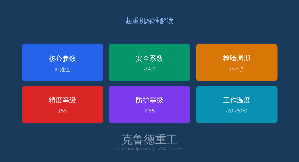
Under FEM 9.661, the design and manufacturing of crane wheels must satisfy a stringent set of technical parameters. These values are derived from extensive test data and safety engineering principles, covering everything from material selection to structural design. The safety factor ranges specified in the standard account for fatigue life and limit load conditions under demanding operating environments. In practical engineering applications, designers select appropriate parameter combinations based on the equipment's work duty classification, load spectrum, and operating conditions. The following parameter cards summarize the standard's core technical indicators:
Comparative Analysis of Key Technical Parameters
The comparison table below systematically contrasts the core parameters specified in FEM 9.661 with general engineering practice. All values shown are either mandatory or recommended clauses of the standard and should be strictly followed during design selection and factory acceptance testing.
| Item | technical requirements | Description |
|---|---|---|
| tread hardness | HB300~380(Hardened Layer) | Case Depth≥20mm |
| contact stress | ≤500N/mm²(Line Contact) | Calculated per Hertz Theory |
| Wheel flange Dimension | Wheel flange Height≥20mm/Thickness≥16mm | Wear>50%Replacement |
| Crane wheel Material | ZG65MnCast Steel/42CrMoAlloy Steel | normalizing+Surface Hardening Treatment |
| wheel load gauge Calculated per Hertz Theory | P≤k·D·B(k=5~8N/mm²) | DWheel Diameter/mm, BTread surfacewidth/mm |
| Wheel Axle Strength | Safety factor≥1.5(Yield) | Rolling Bearing L10≥5000h |
Inspection Requirements and Intervals
FEM 9.661 sets out clear requirements for Factory Acceptance Tests, Type Tests, and periodic inspections under the crane wheel design specification. Factory Acceptance Tests must be carried out on every unit at the manufacturer's facility by the quality inspection department, and each unit that passes must be accompanied by a detailed inspection report and a certificate of conformity. For equipment already in service, the periodic inspection interval is determined by the work duty classification and operating environment, and generally must not exceed 12 months.
| Item | technical requirements | Description |
|---|---|---|
| Tread surface Wear | diameter reduction Measurement | Quarterly+Reduction>3%Replacement |
| Wheel flange Wear | Thickness Measurement | Quarterly+>50%Replacement |
| bearing clearance | Axial/Radial Clearance Detection | Annual+Per SKFStandard |
| Wheel Axle Axial Deviation | Laser Alignment Measurement | Annual+Deviation≤2mm |
Safe Operation and Management Requirements
Safe operation and routine management play a critical role in the implementation of FEM 9.661. The standard places strong emphasis on operator qualification and training, requiring that all operators complete specialized training and obtain the necessary certifications before assuming their duties. User units must establish a comprehensive equipment file management system that documents the full lifecycle of installation, use, maintenance and inspection. Any safety hazards identified must be addressed through the rectification procedure specified in the standard, ensuring that equipment remains in a safe and controllable condition at all times. Additionally, the standard imposes restrictive requirements on equipment operation under extreme operating conditions.
FAQ
Q: What are the tread hardness requirements for crane wheels under FEM 9.661?
A: The standard requires a tread surface hardness of HB300–380 with a hardened layer depth of no less than 20 mm. Common wheel materials include ZG65Mn cast steel or 42CrMo alloy steel, which undergo normalizing followed by surface hardening. Insufficient tread hardness leads to premature wear, while excessive hardness may cause surface spalling. The hardness of the tread surface and wheel flange should be consistent to prevent accelerated flange wear. Kelude Heavy Industry employs a Through Hardening process, maintaining tread hardness within HB320–360.
Q: How is contact stress on crane wheels calculated and controlled?
A: Contact stress on the wheel is calculated using the Hertz line contact formula: σH = 0.418√(P·E/(D·B)), where P is the wheel load, E is the Elastic Modulus, D is the Wheel Diameter, and B is the tread width. The standard requires that contact stress not exceed 500 N/mm². A simplified formula P ≤ k·D·B may also be used, with k ranging from 5 to 8 N/mm². Lower k values apply when the Wheel Diameter is small or the tread is narrow.
Q: What are the discard criteria for crane wheels?
A: The wheel must be replaced when the tread diameter reduction exceeds 3% of the original diameter; when flange thickness wear exceeds 50% of the original thickness; when spalling, cracks, or pitting appear on the tread surface; or when cracks or chipping develop on the wheel flange. If bearing damage causes uneven wheel wear, both the wheel and the bearing should be replaced simultaneously.
Q: What are the installation accuracy and inspection requirements for Wheel Blocks?
A: For four-wheel configurations, the diagonal difference must not exceed 2 mm. The vertical skew of the two wheels on the same End Carriage must not exceed L/1000, and the horizontal skew (parallelism) must also not exceed L/1000. After installation, a no-load run-in and a load test must be performed.
— Specialized in crane design and manufacturing, our products strictly comply with the FEM 9.661 standard system, offering lifecycle service from solution design and manufacturing and installation to after-sales maintenance. For details on how this standard is applied in our products, contact our technical team for comprehensive technical documentation.