

JB/T 7020「起重机用端梁标准」标准解读
📌JB/T 7020《起重机用端梁标准》是起重机领域的重要技术规范。该标准是机械行业制定的起重机端梁专项标准。
This standard provides a unified technical basis for designers, inspection agencies, and users. Krude Heavy Industry strictly adheres to the technical requirements of this standard throughout the product development and manufacturing processes to ensure the equipment’s compliance and reliability.
Scope and Purpose of the Standard
JB/T 7020《起重机用端梁标准》主要规定了起重机起重机用端梁相关的技术要求和安全指标,适用于额定起重量0.5t以上的各类起重机械。该标准不仅覆盖新设备的设计与制造环节,还对在用设备的检验、维护和改造提出了明确的技术指导。作为起重机标准体系中的关键组成部分,该标准与EN 13001系列、ISO 4309等标准协调一致,共同构成了完整的技术规范体系。标准中明确的技术参数和安全系数要求,为设计人员提供了清晰的设计依据,也为第三方检验机构的型式试验和出厂检验提供了可量化的判定标准。
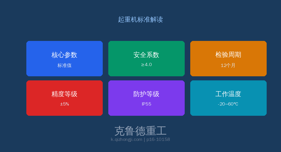
Core Technical Specifications
根据JB/T 7020的技术规定,起重机用端梁标准的设计与制造需要满足一系列严格的技术参数要求。这些参数的确定基于大量试验数据和安全工程理论,覆盖了从材料选用到结构设计的全过程。标准规定的安全系数取值范围充分考虑起重机械在恶劣工况下的疲劳寿命和极限载荷条件。
Comparative Analysis of Key Technical Parameters
| Project | Technical Requirements | Note |
|---|---|---|
| 端梁刚度 | 满载挠度≤L/1000 | 跨中集中载荷工况 |
| 连接螺栓 | 10.9级摩擦型高强螺栓 | 终拧扭矩法+角度法 |
| 轮距公差 | 对角线差≤2mm/轴距差≤3mm | 四轮着轨垫片调整 |
| 水平导向轮 | 间隙2~5mm | 与轨道侧面贴合 |
| 材质 | Q355B(标准)/Q420B(重型) | D/E级低温冲击 |
| 预紧力 | 设计预拉力≥80%极限 | 超拧不超过110% |
Inspection Requirements and Frequency
Factory inspections shall be conducted unit by unit by the quality inspection department at the manufacturer’s facility. Equipment that passes inspection shall be accompanied by a detailed inspection report and a certificate of conformity. Type testing shall be conducted when a new product enters production for the first time, when production is transferred to a different facility, or when major structural changes are made. The periodic inspection interval for in-service equipment shall be determined based on the duty class and operating environment, and generally shall not exceed 12 months.
| Project | Technical Requirements | Note |
|---|---|---|
| 端梁挠度 | Level Surveying | 年度+≤L/1000 |
| 螺栓扭矩 | 扭矩扳手抽检10% | 年度+欠拧补拧 |
| 轮压均衡 | 四轮接触检查 | 年度+垫片调整 |
| 导向轮间隙 | 间隙测量 | 季度+2~5mm |
Safety Operation and Management Requirements
The standard places particular emphasis on the importance of operator qualifications and training, requiring that all operators undergo specialized training and obtain the appropriate qualifications before being allowed to work. Equipment-using entities should establish a comprehensive equipment record management system to document in detail the entire process of installation, use, maintenance, and inspection. Any identified safety hazards must be addressed in accordance with the corrective action procedures specified in the standard to ensure that the equipment remains in a safe and controlled condition at all times.
Frequently Asked Questions
问:JB/T 7020起重机端梁标准对端梁垂直刚度的控制要求?
答:满载L/1000。端梁扭转刚度应足够防止因轨道不平引起的扭转变形。
问:JB/T 7020标准对端梁与主梁连接的高强度螺栓施工要求?
答:10.9级摩擦型高强螺栓。初拧50%+终拧扭矩+角度法。摩擦面≥0.45。10%抽检。
问:JB/T 7020标准对端梁车轮组的轮距和对角线公差要求?
答:对角线≤2mm,轴距≤3mm。四轮同时着轨。三支点垫片调整。
问:JB/T 7020标准对水平导向轮的侧向间隙调整要求?
答:2~5mm,与轨道侧面贴合良好。磨损>10%更换。
🔧 克鲁德重工 — 专注起重机设计与制造,产品严格遵循JB/T 7020标准体系,提供全生命周期服务。
