

GB/T 12602-2020 Overload Protection Devices for Cranes — Standard Interpretation
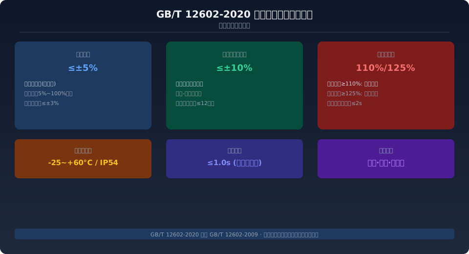
GB/T 12602-2020 Overload Protection Devices for Cranes, issued in 2020 by the Standardization Administration of China (SAC), is the current core safety standard for cranes. Replacing GB/T 12602-2009, it specifies the terminology, technical requirements, test methods and inspection rules for overload limiters and load moment limiters. Jib-type cranes with a rated lifting capacity of ≥3 t must be equipped with a load moment limiter, while overhead (bridge) and gantry cranes must be equipped with an overload limiter; the two types of devices are not interchangeable.
This standard was developed with reference to GB/T 3811-2008 Crane Design Specifications for the requirements on safety protection devices, and complies with TSG 51-2023 Supervision Regulations on Safety Technology for Lifting Appliances mandatory inspection provisions.
Background and Scope of the Standard
GB/T 12602-2020 was jointly issued by the State Administration for Market Regulation and the Standardization Administration of China on 19 November 2020, and officially implemented on 1 June 2021, replacing the GB/T 12602-2009 edition that had been in force for 11 years. The new edition comprehensively upgrades the accuracy grade, dynamic response speed, self-diagnosis function requirements and environmental adaptability of overload protection devices.
The standard applies to overload limiters and load moment limiters installed on overhead (bridge) cranes, gantry cranes, jib-type cranes (mobile, tower, portal, railway cranes, etc.), loader cranes and other types of lifting appliances. It does not apply to overload protection devices for manually operated lifting equipment, elevators, or builders' hoists. The standard is administered by the National Technical Committee on Cranes of Standardization Administration of China (SAC/TC 227).
Kelude Heavy Industry strictly follows the requirements of this standard in the selection and matching of safety protection devices for cranes, equipping every delivered machine with type-test-certified overload protection devices as standard, and providing factory calibration certificates as well as 12-month calibration-due reminder services.
Key Differences Between Overload Limiters and Load Moment Limiters
Kelude Heavy Industry strictly follows the requirements of this standard in the selection and matching of safety protection devices for cranes. GB/T 12602-2020 clearly divides overload protection devices into two categories: overload limiters (sensing only the hoisting load) and load moment limiters (sensing both the hoisting load and the working radius). This division is the most important technical framework of the standard.
An overload limiter typically requires only one load cell (tension, load-pin or torque type), installed at the fixed sheave shaft end, on the hook crossbeam, or on the motor output shaft, back-calculating the actual load by measuring the wire rope tension or motor torque. When the load exceeds 110% of the rated value, it triggers an audible and visual alarm, and when it reaches 125%, it automatically cuts off the power source. A load moment limiter, by contrast, requires at least two sensors — a load sensor and a radius sensor (angle sensor or displacement sensor) — and determines the safety state by calculating in real time the ratio of the load moment to the rated moment.
| Comparison Item | Overload Limiter | Load Moment Limiter |
|---|---|---|
| Number of Sensors | 1 (tension / load-pin / torque) | ≥2 (load + radius) |
| Applicable Crane Type | Overhead, gantry (excluding jib) | Jib-type (mobile / tower / portal, etc.) |
| Overall Error Requirement | ≤±5% (5%–100% of rated load range) | ≤±10% (full working radius range) |
| Alarm Threshold | ≥110% of rated load | ≥100% of rated lifting moment |
| Automatic Cut-off Threshold | ≥125% of rated load | ≥110% of rated lifting moment |
| Response Time | ≤1.0s | ≤1.5 s (including radius calculation) |
Sensor Configuration and Installation Requirements
The performance of overload protection devices depends heavily on the proper selection and installation of sensors. GB/T 12602-2020 specifies clear requirements for the mounting position and protection rating of sensors.
For overhead and gantry cranes, the load cell of an overload limiter is typically installed at the fixed sheave shaft end (with embedded strain gauges measuring the vertical component of wire rope tension), on the hook crossbeam (with a tension load cell connected directly in series), or on the motor output shaft (back-calculating via a torque sensor). The protection rating of the sensor shall be no lower than IP54 (IP65 for outdoor types), and signal cables must be laid independently in steel conduits and kept at a spacing of 300 mm or more from power cables to prevent inverter PWM interference from causing reading jumps. For jib-type cranes, the load moment limiter additionally requires a radius sensor (angle encoder or draw-wire displacement sensor) with an accuracy grade no lower than 0.1°.
IP65 (outdoor)
2 mV/V excitation
Test Methods and Inspection Rules
Chapter 5 of the standard specifies in detail the type test and factory inspection items for overload protection devices. Type tests include the overall error test, actuation point repeatability test, response time test, environmental adaptability test (high temperature +60 °C / low temperature −25 °C / damp heat), electromagnetic compatibility test (IEC 61000-4 series) and mechanical vibration test.
The calibration procedure is the core of the inspection process:
First, install standard weights or a hydraulic loading device and load to 50% of the rated load to calibrate the sensor zero offset.
Then, load to 100% of the rated load and adjust the controller gain so that the reading deviation is ≤±3%.
Next, load to 110% and 125% respectively to verify the alarm and cut-off functions.
Finally, return to zero load under no-load conditions and verify the return-to-zero error (zero offset ≤1% FS).
For jib-type cranes, calibration of the load moment limiter must be verified at three radius points: minimum, medium and maximum boom length.
| Inspection Item | Standard Requirement | Test Method |
|---|---|---|
| Overall Error | ≤±5% (overload limiter) / ≤±10% (load moment limiter) | Load standard weights step by step; take the average of 3 readings |
| Actuation Point Repeatability | Repeatability error ≤±3% | Apply the same load 5 times and calculate the standard deviation |
| Response Time | Overload limiter ≤1.0 s / load moment limiter ≤1.5 s | Sudden load application method; time the electrical signal from loading to alarm |
| Ambient Temperature Test | −25 °C and +60 °C, held for 2 h each | Measure the error at cold/hot extremes in a temperature chamber |
| Electromagnetic Compatibility | IEC 61000-4-2/4/5, level 3 | Electrostatic discharge / burst / surge tests |
| Vibration Test | 10–55 Hz, 0.35 mm amplitude, 10 cycles | Sweep-frequency test after mounting on a vibration table |
Related reading: Difference Between Crane Overload Limiters and Load Moment Limiters: Working Principle, Installation Position, Selection and Calibration Comparison — Technical comparison and selection examples of the two types of overload protection devices
Main Changes in the New Edition
Compared with the 2009 edition, GB/T 12602-2020 contains the following important updates:
First, self-diagnosis function requirements were added — overload protection devices shall have self-detection capability for sensor open circuit, short circuit and zero drift, and shall automatically trigger an alarm signal and record a fault code under fault conditions.
Second, protection rating requirements were raised — indoor types from IP42 to IP54, outdoor types from IP54 to IP65.
Third, a data logging function was added — at least the most recent 100 alarm and cut-off events (including timestamps and load values) must be recorded to facilitate accident traceability.
Fourth, communication interface requirements were clarified — devices shall have an RS-485 or CAN bus interface supporting Modbus RTU or CANopen protocol, for easy integration into a crane safety monitoring and management system.
In new product development, Kelude Heavy Industry has incorporated the self-diagnosis and data logging functions required by GB/T 12602-2020 into its crane safety monitoring and management system as standard configuration, ensuring that every machine meets the requirements of the new standard.
Frequently Asked Questions
Q: What actions should an overload limiter trigger at 110% and 125% respectively under GB/T 12602-2020?
A: When the actual load reaches 110% of the rated load, the overload limiter shall immediately emit a clear audible and visual alarm signal (sound ≥85 dB, red flashing light), but must not cut off the power source. When the actual load reaches 125%, it must automatically cut off the power source of the hoisting mechanism (motor de-energization or hydraulic system unloading), and simultaneously cut off the power of the mechanisms running in the dangerous direction. After cut-off, manual reset is required before operation can resume.
Q: Why can't an overload limiter be used to replace a load moment limiter when installed directly on a jib crane?
A: For an overhead crane, the load is independent of the radius, so an overload limiter can determine overload by measuring only the vertical load. However, the rated lifting moment of a jib crane decreases linearly as the radius increases — at minimum radius it can lift 100 t, while at maximum radius it may be permitted to lift only 20 t. An overload limiter cannot sense the change in radius and might allow a load far exceeding the rated moment to be lifted at a large radius, causing the whole machine to overturn. Therefore, jib-type cranes must be equipped with a load moment limiter that senses both load and radius.
Q: What specific requirements does GB/T 12602-2020 impose on the sensor self-diagnosis function?
A: The self-diagnosis function requirements newly added by the standard include: sensor open-circuit detection (alarm within 2 s when the signal drops to 0 mV), short-circuit detection (alarm when the signal saturates at ≥80% of the excitation voltage), and zero-drift detection (alarm when the no-load reading deviates from zero by more than 3% of full scale). Under fault conditions, the device panel shall display the corresponding fault code (e.g., E01 open circuit / E02 short circuit / E03 drift) and upload the fault information via the communication interface.
Q: What are the calibration interval and mandatory verification requirements for overload protection devices?
A: At the factory, each device must undergo overall error and actuation point tests and be issued with a calibration certificate. After installation and before first use and during use, it must be calibrated at least once every 12 months. Recalibration is required in the following cases: after replacing the sensor or controller, after the overload protection device has experienced a severe mechanical shock, or after the actuation point deviation exceeds ±5% for 3 consecutive times. The overload protection devices fitted as standard on lifting equipment supplied by Kelude Heavy Industry all come with factory calibration certificates, and an automatic calibration-due reminder mechanism has been established.
