ISO 7363 Crane Steel Structure Welding Requirements Explained

Standard Overview: ISO 7363, published by ISO/TC 96 (Cranes — Technical Committee), defines the acceptance criteria for weld quality in crane steel structures. It establishes design principles for welded joints, welding procedure qualification requirements, welder certification criteria, non-destructive testing methods, and acceptance standards. This standard complements the ISO 4301 crane classification system and the ISO 12488 tolerance standard, forming a complete chain of technical specifications from design through final acceptance of crane steel structures.

ISO 7363 weld joint classification
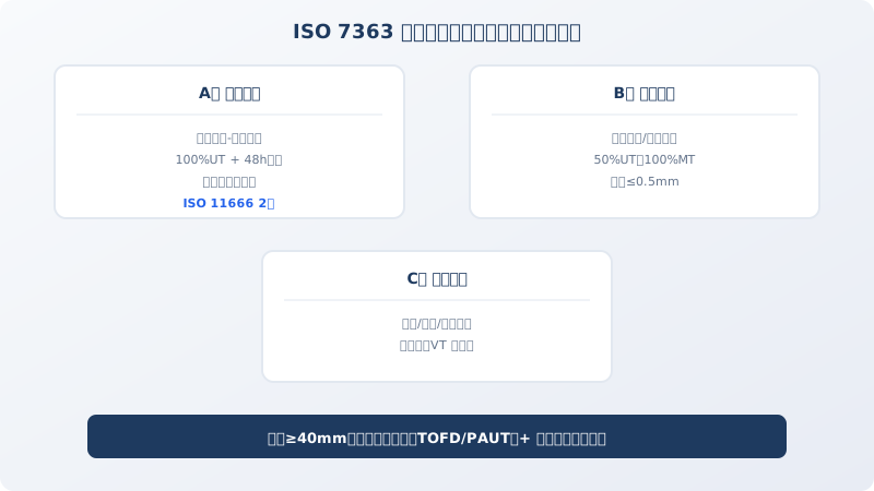
▲ ISO 7363 weld quality level classification diagram

The weld quality of a crane's steel structure directly determines the machine's load-bearing capacity and service life. A double-girder bridge crane with a 30 m span can have over 200 m of main girder weld seams — any lack of fusion or crack can propagate into a fatigue fracture under cyclic loading. ISO 7363 sets out systematic requirements for crane steel structure welded joints, from design selection through non-destructive testing. This article breaks down the core technical provisions of the standard.

Welded Joint Design Principles

ISO 7363 requires that welded joints in crane steel structures be designed on the "equal-strength matching" principle — the mechanical properties of the weld metal must not be lower than the specified values of the base material. For Q355B (≈S355JR) crane main girders, the weld metal must achieve a tensile strength ≥470 MPa, a yield strength ≥345 MPa, and an impact absorption energy ≥34 J at -20°C (consistent with the KV₂ test conditions of the base material).

For joint configuration, the connection between the main girder web plate and flange plate uses double-sided fillet welds, with the leg size taken as 0.7 times the web plate thickness (minimum 6 mm). For highly stressed joints such as the end carriage-to-main girder connection, full penetration butt welds or combined welds (butt + fillet) are recommended to prevent root tearing of plain fillet welds under bending moments. For thick plates ≥30 mm, ISO 7363 requires U-groove or double-V-groove preparations instead of single-V grooves to reduce weld metal volume and minimize residual stress.

Welding Procedure Qualification (WPQR) Requirements

ISO 7363 explicitly requires that all load-bearing welds in crane steel structures undergo welding procedure qualification (WPQR) before production welding, with a qualification report issued. The test coupon material, thickness, and heat treatment condition must match the actual production part. Qualification testing covers tensile tests (determining the tensile strength of both weld metal and the joint), bending tests (2 face bends and 2 root bends, former diameter = 4t, bend angle 180°), impact tests (3 specimens each from the weld center and heat-affected zone), and macroscopic metallographic examination.

Qualification coverage: for base material thicknesses between 3 and 150 mm, a qualified procedure covers actual plate thicknesses in the range of 0.5t to 2t (where t is the test coupon thickness). Any change in filler metal classification (wire/flux combination), a reduction in preheat temperature exceeding 50°C, or a variation in heat input exceeding ±25% requires requalification of the procedure.

Welder Qualification and Operating Regulations

ISO 7363 references ISO 9606-1 (Qualification testing of welders — Fusion welding), requiring that all welding personnel on crane steel structures hold a certificate of competence for the relevant project. Certificates are typically valid for 2 years. The qualification must cover the actual welding process used (e.g., GMAW, FCAW, SAW), joint type (plate butt / pipe butt / T-joint), and welding position (flat / horizontal / vertical / overhead).

For welding of critical components such as main girders, ISO 7363 recommends that welders complete a product-simulated test plate before starting production work. The simulated test plate must be no smaller than 300 mm × 150 mm × base material thickness, and the welder may only begin production after the plate passes non-destructive testing and mechanical property tests. Workshops should establish a welder traceability system — each main weld seam is marked with the welder's stamp number or a unique traceability code, ensuring lifetime traceability of weld quality.

Non-Destructive Testing Methods and Acceptance Criteria

ISO 7363 classifies testing requirements into three levels based on the stress level of the weld:

Level A (Critical welds) — Main girder flange-to-web welds, end carriage connection welds, and hoisting mechanism base welds. 100% Ultrasonic Testing (UT), acceptance level per ISO 11666 Level 2 (individual defect indication length ≤15 mm, cumulative defect length ≤6% of weld length).

Level B (Important welds) — Rail clamp welds, walkway support bracket welds, and guardrail base welds. 50% UT or 100% Magnetic Particle Testing (MT); no cracks, lack of fusion, or undercut deeper than 0.5 mm permitted on the surface.

Level C (General welds) — Non-load-bearing welds such as ladder handrails and cable trays. Visual inspection (VT); no cracks, weld overfill, crater pits, or spatter permitted on the weld surface. Fillet weld leg size deviation ≤+2 mm/-1 mm.

For full penetration welds in plates ≥40 mm thick, ISO 7363 requires delayed crack detection (using TOFD or phased-array UT) 48 hours after welding completion to rule out hydrogen-induced delayed cracking.

Post-Weld Heat Treatment and Residual Stress Control

ISO 7363 stipulates that post-weld stress relief (PWHT) is required when the plate thickness of the crane steel structure exceeds 40 mm (Q355 grade) or 30 mm (Q460 and above), and when residual stress could affect dimensional stability of the structure. Heat treatment parameters: heating rate ≤100°C/h, soaking temperature 550–600°C, soaking time calculated at 1 hour per 25 mm of plate thickness, cooling rate ≤80°C/h, and the part may be removed from the furnace for air cooling only after furnace cooling to below 300°C.

For oversized structures that cannot be furnace-treated as a whole, ISO 7363 permits localized heat treatment — the heating tape width must be ≥ weld width + 6 times the plate thickness (3 times on each side), the soaking zone is insulated with ceramic fiber blanket, and the temperature gradient is controlled within 100°C/150 mm. Vibratory stress relief (VSR) may be used as an alternative for moderately restrained welded structures, but heat treatment remains the primary method for critical load-bearing welds, with VSR serving only as a supplementary measure.

weld quality levelNDTMethodDetection ScaleAcceptance StandardTypical Applications
AClassUT 100%100%Defect Length≤15mmMain Girderflange-Web plate
BClassUT 50%+MT50%Undercut≤0.5mmRail Clamp / Rail Clip/Walkway / Platform
CClassVT Appearance100%Visual InspectionNone Crack/Weld SplatterLadder/Handrail

FAQ: Crane Welding Standards and Defect Control

Q: What are the key differences between ISO 7363 and GB/T 3811 welding requirements?

A: The welding provisions in GB/T 3811 Crane Design Standard primarily reference GB 50661, the Chinese code for welding of steel structures, which focuses on process requirements tailored to domestic steel and filler metal systems. ISO 7363, by contrast, aligns filler metal selection with ISO standards (e.g., ISO 2560 for covered electrodes, ISO 14341 for wire electrodes) and references the ISO 11666 series for non-destructive testing acceptance criteria, which are more specific in their acceptance levels. For export projects or cranes designed to FEM standards, ISO 7363 is typically the governing document for welding acceptance.

Q: What are the most common weld defects in crane fabrication, and how are they addressed?

A: Typical defects include: ① Porosity — usually caused by damp flux or insufficient shielding gas flow; defective areas must be ground out and re-welded. ② Lack of fusion — often the result of an excessively narrow groove angle or low welding current; affected areas must be removed by carbon arc gouging and re-welded. ③ Undercut — typically caused by excessive travel speed; if depth exceeds 0.5 mm, the area requires re-welding and grinding. ④ Cracks — never repair directly by welding; the crack must be completely removed by carbon arc gouging, verified to be free of propagation, and then re-welded, followed by fresh non-destructive testing. At Kelude's steel structure welding workshop, every critical weld seam is subject to a three-tier quality control system: welder self-inspection, dedicated UT inspection, and third-party spot checks.

Q: What special welding requirements apply to crane steel structures in low-temperature environments?

A: When the ambient temperature falls below 0°C, ISO 7363 requires preheating to a minimum of 50°C across a zone extending 100 mm on either side of the groove before welding begins. At temperatures below -10°C, the preheating temperature must be raised to 80–120°C, and the interpass temperature must not drop below the preheating temperature during welding. Low-hydrogen filler metals containing nickel — such as AWS E7018-C1L or ISO E50 4 Ni B 32 — are required to ensure adequate low-temperature toughness of the weld metal. After welding, the joint must be covered with asbestos cloth for slow cooling; forced air cooling or water quenching is strictly prohibited.

Q: How is the leg size of a fillet weld determined?

A: ISO 7363 specifies that the leg size (a) of a fillet weld be determined as follows: for load-carrying fillet welds, a ≥ 0.7t (where t is the thinner plate thickness) with a minimum of 6 mm; for non-load-carrying fillet welds, a ≥ 5 mm. For the connection between the main girder web plate and flange — for example, with an 8 mm web plate and a 12 mm flange — the calculated leg size is a = 0.7 × 8 ≈ 6 mm, but in practice a leg size of 8–10 mm is specified, ensuring a throat thickness of at least a/√2. Oversized legs increase heat input and residual stress, while undersized legs compromise load capacity; therefore, the leg size must be clearly indicated on the workshop drawings.

Related News

contact

contact us

phone:
+86 13903802779

mail:3915269@qq.com

Working hours: Monday to Friday

Wechat
Wechat
SHARE
TOP