

Design of Electrical Grounding and Lightning Protection Systems for Cranes: A Comprehensive Guide to TN-S Grounding, Equipotential Bonding, and SPDs
📌 The electrical grounding and lightning protection systems for cranes are core safety features designed to protect outdoor overhead cranes from lightning strikes and electrical accidents.According to GB 50057, *Code for Design of Lightning Protection for Buildings*, cranes are classified as Category II lightning-protected structures and must be equipped with a lightning rod (protruding ≥1 m above the highest point), utilize the steel structure as a natural down conductor, and have a loop grounding system installed along the entire length of the track (resistance ≤4 Ω). The power distribution system adopts the TN-S system (with separate PE and N wiring), SPD surge protectors are installed on critical circuits, and all metal components are connected via equipotential bonding. The probability of a lightning strike on an outdoor gantry crane is approximately 0.5 to 1 strike per year (based on a height of 30 m and 40 thunderstorm days per year); a comprehensive lightning protection system can reduce the probability of lightning damage to less than 1%.
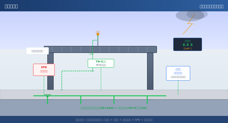
Lightning Protection Classification and Lightning Rod Design
Outdoor overhead cranes are tall metal structures and are classified as Category II lightning-protected structures under GB 50057-2010, “Code for Design of Lightning Protection for Buildings.” Lightning protection requirements must be assessed separately for the crane’s operational and non-operational states: During operation, when an operator is present in the cab, protection is provided using the rolling sphere method with a rolling sphere radius of 45 m; during non-operational periods (when unmanned), the crane’s steel structure serves as a natural lightning rod to carry the lightning current. The lightning strike risk assessment is calculated using the formula: N = k × Ng × Ae, where k is the correction factor (set to 2 for isolated, tall metal structures), Ng is the annual average density of lightning strikes to the ground (strikes/km²·year), and Ae is the equivalent cross-sectional area. For a 30-meter-high gantry crane in a region with 40 thunderstorm days per year, the estimated annual number of lightning strikes is approximately 0.5 to 1.
The lightning arrester is installed at the highest point of the crane, i.e., on top of the trolley or the operator’s cab. The lightning rod is made of stainless steel round bar (diameter ≥ 12 mm) or galvanized steel pipe (DN25) and extends ≥ 1 m above the highest point of the crane. The lightning rod must be securely welded to the crane’s steel structure; the weld length must be no less than six times the diameter of the round bar, the weld bead height must be ≥4 mm, and the weld must be coated with anti-rust paint after welding. In coastal or highly corrosive environments, the corrosion-resistant service life of a stainless steel lightning rod can reach 15–20 years, while that of a galvanized steel pipe is approximately 8–12 years. Where conditions permit, active early-discharge lightning rods (ESE rods) may be installed. Compared to traditional Franklin-type lightning rods, their protection range is expanded by approximately 30%–50%; however, it must be confirmed that the product has passed GB/T 21431 certification.
When the crane is in operation, the operator’s cab itself requires additional protection against direct lightning strikes. An independent lightning protection strip or mesh should be installed on the roof of the operator’s cab, with a mesh size no larger than 5 m × 5 m. The lightning protection strip shall consist of galvanized round steel with a diameter of ≥8 mm or flat steel with a cross-sectional area of ≥48 mm² (thickness ≥4 mm). If the thickness of the cab’s outer metal shell is ≥4 mm, it may serve directly as a lightning receptor; if it is less than 4 mm, a lightning protection band must be installed. All welded connections and anti-corrosion treatments for lightning protection bands and meshes shall comply with the requirements for the main lightning rod. When the crane is not in operation and is parked at its anchored position, the entire steel structure serves as the lightning receptor.
Down conductors are electrically connected to the steel structure
The purpose of a down conductor is to channel the lightning current intercepted by the lightning arrestor into the grounding system. Large metal components of a crane’s steel structure—such as the main girder, end beams, and outriggers—can serve as natural down conductors, eliminating the need to install additional copper cable down conductors. The key is to ensure reliable electrical connections between all metal components—jumper wires must be installed at bolted joints. These jumper wires should consist of copper stranded wire with a cross-sectional area of no less than 50 mm², crimped at both ends with copper terminals, and the bolt tightening torque must comply with the GB/T 1228 standard. The total resistance of the down conductor from the lightning rod to the grounding system should not exceed 1 Ω; this can be measured at each connection point along the down conductor using a ground resistance tester.
The jumper wires should be installed to cover all non-welded connection points: the bolted connection between the main girder and the end girder, the flange connection between the end girder and the legs, the connection between the trolley frame and the wheel set, and the connection between the operator’s cab and the main girder. One jumper wire shall be installed at each connection point. The wire shall be BVR-50 mm² yellow-green copper-core flexible cable, protected by a flame-retardant corrugated sleeve. The bending radius of the jumper cables shall be no less than six times the cable’s outer diameter, with 200 mm of slack left at both ends to prevent breakage due to tension during operation. Krude Heavy Industry installs conspicuous grounding identification tags at both ends of each jumper cable to facilitate regular inspections of the connection status by maintenance personnel.
The conductor rail system must also be incorporated into the down conductor path. A grounding connection point is installed on the conductor rail housing every 10 meters, and it is securely connected to the crane’s main girder steel structure using BVR-16mm² yellow-green wire. The metal armor layer of the cable must be grounded at both ends, with additional grounding every 50 meters along the intermediate section to ensure that the potential of the armor layer is equal to that of the steel structure. For information on the overall architectural design of the overhead crane’s electrical control system and PLC program debugging methods, please refer to the articles in this series.The Complete Process of Designing an Overhead Crane Electrical Control System: From Schematic Design to PLC Program Debugging—Engineering Practice. In applications powered by a variable-frequency drive (VFD), the cable shield must also be properly grounded for EMC purposes—using a 360° loop grounding connection on the VFD side and HF grounding (high-frequency capacitive coupling grounding) on the motor side to suppress harmonic interference propagating along the shield.
Design of Grounding Systems and Grounding Resistance
The crane’s grounding system consists of horizontal and vertical grounding electrodes arranged along the entire length of the track. Horizontal grounding electrodes shall be made of galvanized flat steel (-40 mm × 4 mm) or galvanized round steel (diameter ≥ 12 mm), buried to a depth of no less than 0.8 m and located no less than 0.5 m from the edge of the rail foundation. Vertical grounding electrodes shall be made of galvanized angle steel (∠50 × 50 × 5 mm, length L = 2.5 m), arranged uniformly at 5-meter intervals, with a minimum of four electrodes. The top of the angle steel shall be at least 0.8 m above ground level; the angle steel shall be welded to the horizontal grounding electrodes, and anti-corrosion treatment shall be applied after welding. The grounding resistance of the entire grounding system shall be ≤4 Ω; in areas with high soil resistivity, this may be relaxed to ≤10 Ω, provided that equipotential bonding is implemented.
The connection between the rails and the grounding device is the final link in the grounding system. One grounding connection point is provided at each end of each rail; the rails are connected directly to the horizontal grounding electrode by welding or bolted crimping using BVR-50mm² copper stranded wire. One grounding jumper connection is provided on each side of the rail joint (fishplate connection), with the jumper wire having a cross-sectional area of no less than 50 mm². A repeat grounding connection point is provided every 30 m along the length of the track. At rail expansion joints, the bonding conductor shall have sufficient slack (≥150 mm arc-shaped bend) to accommodate thermal expansion. The contact resistance at all grounding connection points shall not exceed 0.03 Ω, as verified by measurement with a microohmmeter.
Ground resistance measurements are performed once after construction is completed and once before each annual thunderstorm season. The three-electrode method is used (with a ground resistance tester, such as the Fluke 1625), with the current electrode and potential electrode spaced equally at C: 20 m and P: 15 m, respectively. During measurement, the crane must be in a non-operational state, and all grounding connection points must be properly connected. If the measured resistance exceeds 4 Ω, measures must be taken to reduce resistance—such as increasing the number of vertical grounding electrodes, using resistance-reducing agents (such as bentonite or chemical resistance reducers, with a reduction rate of approximately 30% to 50%), or increasing the length of the horizontal grounding electrodes. In rocky areas, soil replacement backfilling may be considered (replacing the original foundation soil with soil of lower resistivity).
Equipotential Bonding and Shunting
| Equipotential Objects | Specifications for Jumper Wires | Connection Methods | Testing Requirements |
|---|---|---|---|
| Bolt Connections for Main Beams, End Beams, and Legs | BVR-50 mm² Copper Stranded Wire | Copper Terminal Crimping + Bolt Fastening | Torque in accordance with GB/T 1228 |
| Sliding Contact Rail Housing | BVR-16mm² Yellow-Green Wire | Install a grounding connection point every 10 meters. | Visual Inspection + Tightening |
| Metal Components for the Driver's Cab / Doors and Windows | BVR-6 mm² wire | Connect to the equipotential terminal block | Ground continuity ≤ 0.2 Ω |
| Wire Rope and Hook | Grounding conductor ≥ 4 mm² | Grounding Brush (Pressure ≥ 15 N) | Annual Inspection of Continuity |
| Both sides of the insulating component (buffer/coupling) | BVR-10mm² Jumper Wire | Crimp the bolts at both ends | No rust or corrosion was observed during visual inspection. |
There is another often-overlooked component of equipotential bonding: electrical continuity between the wire rope and the hook. Electrical continuity must be ensured between the hook and the wire rope to prevent electrostatic discharge when the hook approaches the load. Install a grounding brush (carbon or copper brush, with a contact pressure of ≥15 N) at the connection point between the wire rope and the hook; the cross-sectional area of the grounding conductor must be no less than 4 mm². The metal pulleys in the pulley block must also be incorporated into the equipotential bonding system; a BVR-6 mm² flexible cable should be used to bond the pulley bearing housings to the trolley frame. On both sides of insulated components such as rubber buffers and flexible couplings, install one BVR-10 mm² bonding conductor on each side.
TN-S Power Distribution and SPD Surge Protection
The crane’s low-voltage power distribution system should use the TN-S system (three-phase, five-wire system), meaning that the working neutral conductor (N) and the protective earth (PE) are completely independently wired starting from the transformer neutral point, and the PE conductor is double-grounded at the crane’s feeder panel. The core advantage of the TN-S system is that no current flows through the PE conductor during normal operation (current in the N conductor does not pass through the PE conductor), and the enclosures of all equipment are directly connected to the grounding system via the PE conductor. In the event of an insulation breakdown, the fault current flows through PE to the grounding point, forming a short-circuit loop that triggers the upstream circuit breaker or fuse to trip, thereby isolating the faulty circuit. The minimum cross-sectional area of the PE conductor is specified in GB 50054 as follows: when the phase conductor cross-sectional area S ≤ 16 mm², PE = S; for S > 16 mm²< S ≤35mm²时PE=16mm²,S>When the cross-sectional area is 35 mm², PE = S/2.
Surge protection devices (SPDs) are installed inside the crane’s incoming power distribution cabinet and at the power inputs of critical equipment. A Class I SPD (10/350 μs waveform, impulse current Iimp ≥ 25 kA) is installed at the main circuit breaker in the incoming power distribution cabinet to dissipate the massive surge energy generated by direct lightning strikes. Class II SPDs (8/20 μs waveform, nominal discharge current In ≥ 20 kA) are installed at the power inputs of critical equipment (PLCs, variable frequency drives, encoders, and sensors) to further reduce the residual voltage to a level that the equipment can withstand (<1.5 kV). The SPD wiring length shall not exceed 0.5 m and shall follow the star-connection principle of "L/N → SPD → PE." An overcurrent protector (circuit breaker or fuse, with a rated current not exceeding the SPD’s maximum backup protection value) shall be installed upstream of the SPD.
Signal lines also require SPD protection—signal SPDs should be installed at both ends of PLC analog input signals (4–20 mA), encoder pulse signals, communication buses (PROFINET, RS485), and sensor signal lines. Signal SPDs should have a nominal discharge current (In) of ≥5 kA, a response time of ≤1 ns, and insertion loss of ≤0.5 dB. Output reactors and dv/dt filters must also be installed on the inverter’s output cables to suppress spike voltages generated by the inverter’s PWM waves from coupling into the motor’s insulation and grounding systems. All SPDs should be equipped with a status indicator window (green = normal, red = fault); the indicator status should be checked once a year before the start of the thunderstorm season.
Inspection, Maintenance, and Thunderstorm Season Checks
Inspection and maintenance of the lightning protection grounding system are performed on an annual basis. A comprehensive inspection is conducted once a year before the thunderstorm season (March–April), covering the following items: measurement of grounding resistance (three-electrode method, standard value ≤ 4 Ω), testing the electrical continuity of down conductors (total resistance ≤ 1 Ω), visual inspection of bonding conductors (for corrosion, looseness, or broken strands), and checking the tightening torque of bolts on equipotential busbar terminals (M8 bolts: torque ≥ 20 N·m; M10 bolts: torque ≥ 35 N·m). Record and file the inspection results to establish a lightning protection system health record. If the grounding resistance fails to meet standards for two consecutive years, the grounding system must be upgraded.
During routine inspections, focus on three areas prone to damage. First, the connection points between the jumper wires and the steel structure—bolts are prone to loosening in vibrating environments, so they should be retightened at least once a year and coated with thread-locking adhesive (Loctite 243, medium strength). Second, the grounding connection points of the sliding contact lines—the sliding contact line housing vibrates continuously during operation, and the grounding bolts may fracture due to fatigue. Third is the equipotential bonding in the driver’s cab—since the driver’s cab features a flexible suspension structure, the movement of the cab may cause the cable insulation to wear down. Add a visual inspection of the grounding lines to the monthly equipment inspection to check for visible defects such as broken wires, oxidized joints, or damaged insulation.
Lifecycle management of SPDs is equally important. Grounding inspections and insulation tests conducted during on-site commissioning of electrical systems ensure the reliable operation of lightning protection systems. Please refer to the articles in this series.On-Site Commissioning of Crane Electrical Systems: From Beginner to ExpertInsulation testing methods. The varistors and gas discharge tubes built into SPDs gradually degrade after sustained exposure to surge impacts; their typical design life is 5 to 8 years (or they should be replaced after withstanding a cumulative total of 20 nominal surges). Replace the SPD immediately if the status indicator window turns red; for SPDs without an indicator window, use an SPD tester to check for leakage current annually before the thunderstorm season (replace if the varistor leakage current exceeds 1 mA or if a short circuit is detected). The power supply must be disconnected before replacing an SPD; live operation is strictly prohibited. Krude Heavy Industry’s lightning protection systems are delivered with SPD spare parts (one Class I and one Class II SPD spare part per unit) and a testing log sheet; users simply need to record data quarterly according to the log sheet.
Frequently Asked Questions
Q: What is the grounding resistance value for crane lightning protection?
Answer: According to the GB 50057-2010 standard, the lightning protection grounding resistance for outdoor cranes should not exceed 4 Ω. In high-resistance areas where soil resistivity exceeds 500 Ω·m, this limit may be relaxed to 10 Ω, provided that equipotential bonding measures are implemented simultaneously. Measurements should be performed using a three-electrode ground resistance tester (such as the Fluke 1625) once a year before the start of the thunderstorm season. If the system fails to meet the requirements for two consecutive years, the grounding system must be upgraded.
Q: Is it necessary to install a lightning rod for crane lightning protection?
Answer: Yes. According to the GB 50057 standard, cranes are classified as Category II lightning protection structures and must have a lightning rod installed at their highest point. The lightning rod must be made of stainless steel round bar (diameter ≥ 12 mm) or galvanized steel pipe (DN25), extend at least 1 m above the highest point of the crane, and be securely welded to the steel structure. If the metal sheet on the top of the operator’s cab is ≥4 mm thick, it may also be used directly as a lightning receptor. When the crane is not in operation, the steel structure of the crane body may serve as a lightning receptor as a whole.
Q: Why is the TN-S system recommended for overhead crane power distribution systems?
Answer: In the TN-S system (three-phase, five-wire system), the PE conductor and the N conductor are routed separately. The PE conductor carries no current during normal operation, and the enclosures of all equipment are connected directly to the grounding system via the PE conductor. In the event of an insulation breakdown, the fault current forms a short-circuit path through the PE conductor, triggering the circuit breaker to trip rapidly. Compared to the TN-C system (three-phase four-wire system), the TN-S system eliminates the risk of equipment enclosures becoming energized due to a broken PEN conductor, making it the preferred grounding system for applications with high safety requirements, such as cranes.
Q: How often should an SPD surge protector be replaced?
Answer: Replace the SPD after 5 to 8 years of service life or after it has withstood a cumulative total of 20 nominal surges. If the SPD with a status indicator window shows red, replace it immediately (do not continue to use it). For SPDs without an indicator window, use a tester to check for leakage current annually before the thunderstorm season. Replace the SPD if the varistor’s leakage current exceeds 1 mA or if a short circuit is detected. Replacement must be performed with the power disconnected; do not perform the operation while the system is energized. For SPDs connected to the power supply terminals of inverters and PLCs, prioritize models equipped with remote alarm contacts, which can be integrated into a remote monitoring system.
