Crane Buffer Terminology Explained per GB/T 16564 Standard

GB/T 16564, "Terminology for Crane Buffers," serves as the foundational terminology standard for crane buffers in China's lifting appliance industry. It systematically defines the classification names, structural terms, performance parameters, and test methods for various crane buffers, providing a unified vocabulary for buffer design, selection, manufacturing, and inspection. The standard is administered by the National Technical Committee for Standardization of Lifting Appliances (SAC/TC 227).

Buffers are critical components within a crane's safety protection system. Their primary function is to absorb the kinetic energy generated during crane operation, prevent structural damage from collisions, and ensure personnel safety. When a crane bridge or trolley reaches the end of its travel, or when two cranes unexpectedly approach each other during operation, the buffer converts kinetic energy into heat, elastic potential energy, or other forms through its own deformation, enabling smooth deceleration and stopping. GB/T 16564 was developed to standardize the terminology for this vital component, with its vocabulary covering every stage from design concepts to Factory Acceptance Tests. Kelude Heavy Industry applies buffers conforming to this standard across its Bridge Crane and Gantry Crane products, ensuring reliable end-of-travel protection.

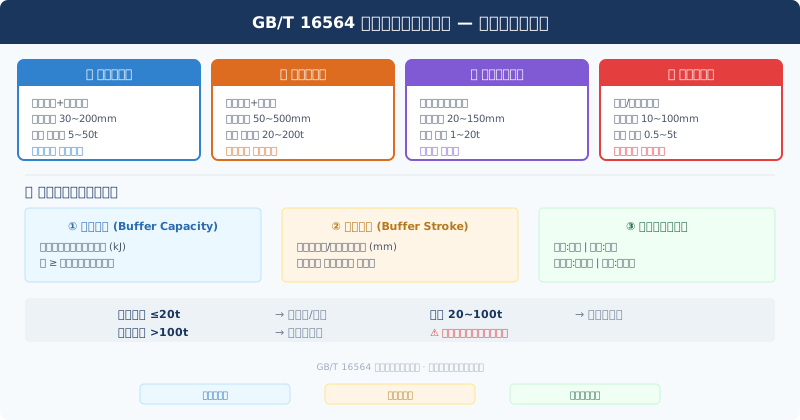
GB/T 16564 buffer terminology classification and selection system diagram

Standard Scope and Terminology Hierarchy

GB/T 16564 applies to all types of buffers used on cranes, including but not limited to travel mechanism buffers, hoisting mechanism buffers, and buffers for special working conditions on Bridge Cranes, Gantry Cranes, Tower Cranes, Jib Cranes, and Mobile Cranes. The standard does not cover buffers for elevators (which are governed by GB 7588), vehicle bumpers, or seismic damping devices for buildings, as these fall outside the scope of lifting appliances.

The terminology system is structured into three levels. The first level comprises general terms that define fundamental concepts applicable to all buffer types, such as "buffer," "buffer stroke," and "energy absorption capacity." The second level consists of classification terms that categorize buffers by their energy absorption principle, including hydraulic buffers, spring buffers, polyurethane buffers, rubber buffers, and pneumatic buffers, each with its own dedicated definition. The third level includes performance parameter terms like "maximum buffer force," "buffer efficiency," "reset time," and "permissible impact speed," providing standardized parameter names and definitions for buffer design calculation and performance testing.


Buffer Classification and Type Characteristics

According to the classification system in GB/T 16564, buffers are first divided into two main categories based on their energy absorption principle: energy-dissipating and energy-storing. Energy-dissipating buffers convert impact kinetic energy irreversibly into heat through the throttling damping of internal fluid (Hydraulic Oil) or the viscoelastic deformation of polymer materials, without returning energy to the crane after impact. Energy-storing buffers temporarily store impact kinetic energy through the compression of springs or elastomers, releasing this stored energy and causing rebound after the impact. From a safety perspective, energy-dissipating buffers offer smoother braking and produce less secondary impact on the structure, making them the preferred choice for high-speed, heavy-load cranes.

Hydraulic buffers are a typical example of energy-dissipating buffers. Their working principle involves a Piston Rod pushing Hydraulic Oil through an Orifice when the crane's travel mechanism impacts the buffer. The resistance to oil flow generates a damping force proportional to the square of the velocity. GB/T 16564 defines key terms for hydraulic buffers: the rated buffer stroke refers to the displacement of the piston from its free state to full compression, typically ranging from 50 to 400 mm; the maximum buffer force is the peak reaction force generated at full piston compression, adjustable by configuring the Orifice area; buffer efficiency is defined as the ratio of actual energy absorbed to the theoretical maximum, with high-quality hydraulic buffers achieving efficiencies above 85%.

Spring buffers are the most common type of energy-storing buffer, valued for their simple structure, low cost, and ease of maintenance. GB/T 16564 defines specific terms for spring buffers: free height is the total length of the buffer spring under no load, pitch is the center-to-center distance between adjacent coils, and solid height is the length of the spring when fully compressed. The buffer efficiency of spring buffers typically ranges from 50% to 65%, which is lower than that of hydraulic buffers. However, their high reliability and leak-free operation make them the most widely used type in small and medium-sized cranes. Polyurethane buffers are a newer type of elastic material buffer that has gained rapid adoption. They absorb energy through the compressive deformation of polyurethane elastomers, offering advantages such as light weight, oil and corrosion resistance, and maintenance-free operation. However, their buffer efficiency is significantly affected by Ambient Temperature, with hardness increasing by approximately 30% at -20°C.


Core Performance Parameter Definitions

Buffer performance evaluation relies on a series of standardized parameters, for which GB/T 16564 provides precise definitions. "Buffer stroke" is the displacement distance traveled by the buffer from initial contact during impact to full compression and stopping. It is a key indicator determining the buffer's installation space and selection. The standard mandates that the buffer stroke be clearly indicated on design drawings, and the measured deviation during the Factory Acceptance Test must not exceed ±2%. "Energy absorption capacity" (or energy absorption capability) is defined as the maximum kinetic energy a buffer can safely absorb in a single impact under rated operating conditions, expressed in kilojoules (kJ). This parameter determines the ultimate impact load the buffer can withstand.

"Maximum buffer force" is the most critical safety parameter in buffer selection, referring to the maximum reaction force the buffer exerts on the crane throughout the entire buffer stroke. This value directly influences the structural design of the crane's End Carriage and the load capacity of the Crane Rail. GB/T 16564 requires manufacturers to indicate the maximum buffer force on the product nameplate. During selection, users must ensure that the buffer's maximum buffer force does not exceed the permissible load of the crane's End Carriage or bogie structure. The shape of the buffer force-stroke characteristic curve is also an important basis for distinguishing the performance of different buffer types – hydraulic buffers exhibit a rectangular characteristic curve (nearly constant force), while spring buffers show a linearly increasing characteristic curve.

Hydraulic Buffer
Energy-Dissipating
Efficiency ≥85%
Spring Buffer
Energy-Storing
Efficiency 50~65%
Polyurethane Buffer
Elastomeric Type
Oil & Corrosion Resistant
Buffer Stroke
50~400mm
Deviation ≤±2%
Energy Capacity
Max. per unit
kJ
Max. buffer force
≤ End carriage allowable load
Must be stated on nameplate

Buffer Selection and Engineering Applications

In practical engineering selection, choosing the right buffer requires a comprehensive evaluation of crane travel speed, total machine mass, work duty, and installation space. While ISO 4301 does not directly provide selection calculation formulas, its standardized terminology system offers a unified language for selection calculations. The fundamental principle is that the buffer's energy absorption capacity must exceed the maximum kinetic energy generated during a full-load, full-speed impact. Taking a 50t bridge crane as an example: with cross travel and crane bridge speeds of 60m/min and 20m/min respectively, and a fully loaded trolley mass of approximately 60t, the impact kinetic energy in the crane bridge direction is calculated as E=0.5×m×v²=0.5×60000×(1.0)²=30kJ. The selected buffer must have an absorption capacity of no less than this value.

For cranes operating in special environments, additional factors must be considered during buffer selection. In high-temperature settings such as metallurgical casting workshops, hydraulic buffers require flame-retardant synthetic ester hydraulic oil, and seals must be made of fluororubber (temperature resistance: -20°C to +200°C). Spring buffers used in high-temperature environments (>200°C) require tempering stability evaluation of the spring material. In coastal ports with high salt-spray exposure, the buffer housing and piston rod should undergo salt-spray-resistant treatment (hard chrome plating with thickness ≥30μm or 316L stainless steel), and polyurethane materials must use hydrolysis-resistant formulations. ISO 4301 requires manufacturers to clearly specify the applicable environmental conditions for each buffer type in their technical files.


Buffer Standard System Comparison

Comparison Items GB/T 16564 JB/T 8110.1/8110.2 ISO 22725
Standard Nature Terminology Standard Productstechnical specification International Technical Requirements Standard
Core Content Term Definition and Classification Technical Parameters/test method/Inspection Rules Bufferdesign principlesandperformance requirements
Buffer Typescoverage Full Product Range Buffer Spring/Hydraulic/Separate Provisions for Polyurethane, etc. Hydraulic/Spring/Polyurethane/Pneumatic Pressure
Energy Absorption Capacitytest method Term Definition Only Drop Hammer Test Method/speed Method Dynamic Impact Test Rig Test
manufacturing precision Requirements No Specific Tolerance Stroke/Travel Tolerance±2%/Force Value±5% Stroke/Travel Tolerance±3%/Force Value±8%
Test Verification Specification Definition Test Terminology Type Test+routine test Detailed Procedure Type Test Reference Method

Buffer Types and Their Operating Conditions at a Glance

Buffer Types Energy Principle Buffer efficiency applicable speed Scope
Hydraulic buffer Throttling Damping Energy Dissipation ≥85% 0.5~3.0 m/s
Spring buffer Elasticity Energy Storage and Rebound 50%~65% 0.3~1.5 m/s
Polyurethane buffer Elasticity Volumetric Compression Energy Storage 60%~75% 0.2~1.2 m/s
Rubber buffer Viscous Elasticity Deformation Damping Energy Dissipation 55%~70% 0.1~0.8 m/s
Pneumatic Pressure Buffer Gas Compression+Damping Energy Dissipation 70%~85% 0.5~2.5 m/s
Combined Type Buffer Hydraulic+Spring Multi-Stage Composite 80%~90% 0.5~4.0 m/s

Inspection & Test Terminology

GB/T 16564 defines the terminology for buffer inspection and testing, providing the conceptual foundation for the test procedures specified in downstream product standards such as the JB/T 8110 series. Within this framework, a "Type Test" is a comprehensive verification of a buffer's design, covering buffer performance testing (measuring the buffer force-stroke curve), durability testing (no fewer than 10,000 consecutive impact cycles), and environmental adaptability testing (temperature cycling and salt spray tests). A "Factory Acceptance Test" (FAT), on the other hand, is the basic performance inspection that every buffer must pass before leaving the factory, including at minimum a visual inspection, dimensional verification, and measurement of the buffer force-stroke curve.

Static compression testing and dynamic impact testing are the two fundamental methods used to evaluate buffer performance. In a static compression test, a hydraulic testing machine compresses the buffer in a quasi-static manner to determine the force-displacement relationship and the maximum compression force. While straightforward to perform, this method cannot assess the buffer's dynamic behavior under high-speed impact. A dynamic impact test, by contrast, uses a drop weight or launcher to strike the buffer at its rated impact speed while recording the force and acceleration time histories. This approach more accurately reflects real-world operating conditions and is a mandatory requirement for Type Tests. GB/T 16564 explicitly states that when the results of the two test methods deviate by more than 15%, the dynamic impact test results shall prevail.


Frequently Asked Questions

Q: What is the fundamental difference in terminology between spring buffers and hydraulic buffers as defined in GB/T 16564?

A: The essential difference lies in how "buffer efficiency" is defined for each type. For spring buffers (energy-storage type), buffer efficiency is defined as the ratio of elastic energy released during the return stroke to the energy absorbed during the compression stroke, typically ranging from 50% to 65%, with the remaining energy returned to the crane as rebound. For hydraulic buffers (energy-dissipation type), buffer efficiency is defined as the ratio of irreversibly dissipated energy to the total absorbed energy; high-quality units can achieve efficiencies above 85%, with minimal rebound energy. This terminological distinction is critical during selection — for cranes requiring precise stop positioning, hydraulic buffers with high buffer efficiency should be the preferred choice.

Q: How do GB/T 16564 and the JB/T 8110 standard series relate to each other in the buffer industry?

A: GB/T 16564 is a terminology standard that addresses the "what to call it" aspect — defining classification names, structural terms, and performance parameter names for buffers. The JB/T 8110 series (including JB/T 8110.1 for spring buffers and JB/T 8110.2 for hydraulic buffers) are product standards that address the "how to build it" aspect — specifying technical parameter limits, test methods, and inspection rules. The two work in tandem: when referencing terminology, use the standardized wording from GB/T 16564; when designing, manufacturing, and inspecting products, follow the product requirements of JB/T 8110.

Q: How can the GB/T 16564 terminology system be used for parameter matching during crane buffer selection?

A: Selection should follow the standard terminology defined in GB/T 16564 in a step-by-step process: first, determine the required "buffer stroke" range based on the crane's installation space; second, calculate the impact kinetic energy based on travel speed and total machine mass, then select a model whose energy absorption capacity exceeds the calculated value; third, verify that the maximum buffer force does not exceed the allowable load of the end carriage structure; and finally, confirm that the buffer's ambient temperature rating and protection rating (IP) match the operating conditions. Every parameter match is performed using standard terminology to avoid selection errors caused by ambiguous naming.

Q: Does GB/T 16564 cover terminology for newer buffer types such as polyurethane buffers?

A: The latest revision of GB/T 16564 has incorporated polyurethane buffers into its terminology framework, defining dedicated terms such as "polyurethane buffer," "elastomeric buffer element," and "hardness-temperature characteristic curve." In the standard, polyurethane buffers are classified as elastomeric energy-storage buffers, with their nominal hardness expressed as a Shore A durometer reading, typically in the A70 to A95 range. The standard also distinguishes between "dynamic stiffness" and "static stiffness" — under high-strain-rate impact, the dynamic stiffness of polyurethane material can be 30% to 60% higher than its static stiffness. This terminological distinction is essential for accurately evaluating the dynamic performance of buffers.

GB/T 16564, "Terminology for Crane Buffers," serves as the terminological cornerstone of China's crane buffer industry, providing a unified conceptual framework for technical communication, standard referencing, contract compliance, and international trade. From the simple energy storage of spring buffers to the precision damping of hydraulic buffers and the engineering application of polyurethane materials, buffer technology continues to evolve — yet a consistent, standardized terminology system remains the foundation for technical continuity and innovation. Industry players should strictly apply the GB/T 16564 terminology throughout the entire product lifecycle, from design drawing annotations to Factory Acceptance Test Reports, from product nameplate data to user Operation Manuals, ensuring that every technical statement is accurate and consistent, so that the selection, use, and maintenance of buffers — the "last line of defense for safety" — are always grounded in clear, unambiguous standards.

Related News

contact

contact us

phone:
+86 13903802779

mail:3915269@qq.com

Working hours: Monday to Friday

Wechat
Wechat
SHARE
TOP