ASME B30.28 Balancer Safety Standard Explained
Standard Overview: ASME B30.28, the Safety Standard for Balanced Lifting Devices, is a dedicated lifting spreader safety standard published by the American Society of Mechanical Engineers (ASME). It covers the design, manufacture, inspection, and safe use of various balanced lifting devices, including lifting beams, spreader beams, C-hooks, vacuum lifters, and magnetic lifting devices. As Volume 28 of the ASME B30 Crane Safety Standards series, it applies to all lifting devices used within the United States.
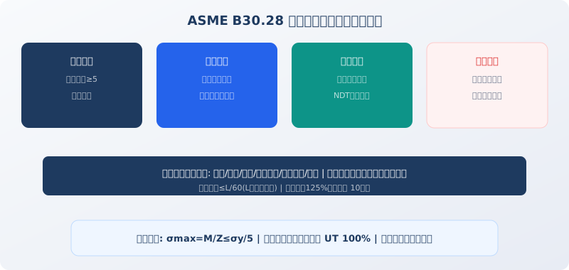
Balanced lifting devices serve as the critical link between the crane and the load — the "last meter" of the lifting chain. Lifting beams, spreader beams, lifting frames, and specialized fixtures between the hook and the object distribute the crane's single-point lifting force into a multi-point balanced system. ASME B30.28 establishes a comprehensive safety management framework covering the entire lifecycle of lifting devices across four key dimensions: design safety, operational safety, inspection safety, and maintenance safety.
Design Safety Requirements for Lifting Devices
ASME B30.28 mandates a minimum safety factor of 5 for steel structures in balanced lifting devices, calculated relative to the material's yield strength. For example, a lifting beam fabricated from Q345B steel (≈S355J2) would have an allowable stress of σallow = 345/5 = 69 MPa. The pin hole diameter of lifting lugs must not exceed the shackle pin diameter by more than 3 mm, preventing impact loads caused by pin movement within the hole. Lifting lug welds must be full penetration butt welds or combined welds (butt weld plus double-sided fillet weld), with 100% UT inspection of the weld seam.
Adjustable spreader beams must incorporate a "redundant locking" mechanism for their adjustment system — at least two independent mechanical locking devices (e.g., pin plus nut, or ratchet plus locking screw) so that if one locking device fails, the other maintains the set position. This requirement represents a core safety philosophy that distinguishes ASME B30.28 from general steel structure design standards.
Pre-Use Inspection and Rated Load Marking
ASME B30.28 requires each balanced lifting device to have a permanently affixed nameplate in a conspicuous location. The nameplate must include: manufacturer name, model/serial number, rated load (WLL), dead weight, and inspection date. The nameplate must be permanently attached (riveted or welded) — wire ties or adhesive mounting are not permitted. Rated load lettering must be at least 10 mm in height.
A visual inspection must be performed before each use, covering: wear on lifting lugs and load point pins (diameter reduction must not exceed 5% of the original), surface cracks in weld seams (with particular attention to lug connection welds and main girder splice welds), and the reliability of the adjustment mechanism's locking devices (manually verifying each locking point is in the locked position). Inspection results are recorded in the Daily Spreader Inspection Checklist, with the inspector's signature confirming completion.
Periodic Inspection and Load Testing
ASME B30.28 requires a comprehensive inspection of balanced lifting devices at least once per year. The inspection includes: MT (magnetic particle) or PT (penetrant) testing of critical weld seams; precision measurement of lifting lug pin hole diameters (rejection if the hole exceeds 5% of the original diameter); and a load test — lifting 125% of the rated load to a height of 100–200 mm and holding for 10 minutes, followed by a check for permanent deformation. The device fails the test if permanent deformation in any direction exceeds L/500 (where L is the lifting beam length).
For vacuum lifters, in addition to structural inspection, the vacuum system's pressure-holding capability must be tested — with the rated load applied and the vacuum pump shut off, vacuum decay must not exceed 20% within 30 seconds (e.g., if initial vacuum is -80 kPa, it must remain at or above -64 kPa after 30 seconds). For magnetic lifting devices, a Tesla meter must be used to measure magnetic flux density at the pole faces; if the reading falls below 90% of the nameplate value, the device must be demagnetized and re-magnetized.
| Inspection Item | Period | Method | Acceptance Criteria |
|---|---|---|---|
| visual inspection | Daily | Visual Inspection+Hammer Tapping Test | No Visible Crack/Deformation |
| Weld Seam NDT | Annually | MT/PT | None Crack/Lack of Fusion |
| Pin Hole Wear | Annually | Inside Micrometer | Bore Diameter Increase≤5% |
| load test | Annually/Overhaul After | 125%Load10min | Deformation≤L/500 |
FAQ
Q: How do multi-point lifting beams ensure uniform load distribution across all lift points?
A: A rigid-body balancing beam (rigid beam with fixed lift points) distributes loads among lift points theoretically according to the lever principle, based on each point's position relative to the load's center of gravity — it cannot actively equalize loads. To achieve uniform load distribution, a pulley-compensating or hydraulic-equalizing beam is required. Pulley-compensating beams use movable pulley blocks to automatically balance wire rope tension across branches (similar to the equal-arm lever principle of a scale). Hydraulic-equalizing beams connect equal-bore hydraulic cylinders in series at each lift point with interconnected oil circuits; the physical property of equal pressure in all cylinders ensures identical load at each point. ASME B30.28 recommends using an equalizing beam when the number of lift points is ≥4, or when the spacing deviation between lift points exceeds 20% of the average spacing, to prevent overloading of individual points.
Q: Is it safe to lift glass with a vacuum lifter? What happens if suction is lost?
A: ASME B30.28 requires vacuum lifters to be equipped with triple protection: ① Vacuum sensor — when vacuum drops below the set point (typically -60 kPa), an audible and visual alarm triggers and hoisting is automatically cut off, allowing lowering only; ② Accumulator (vacuum reservoir) — maintains holding pressure for at least 5 minutes after a vacuum pump power failure, giving the operator sufficient time to safely lower the load; ③ Redundant suction cups — the actual number of cups is twice the calculated requirement, so that if any single cup fails, the remaining cups still retain more than 50% of the total holding force. Vacuum lifters must never be used to lift or transport personnel — standing on a suction cup is strictly prohibited.
Q: Will a magnetic lifter drop a steel plate if power is lost?
A: An electromagnetic spreader (which generates magnetic force via an energized coil) loses all magnetic force the instant power is cut — the load releases immediately. ASME B30.28 therefore mandates two safeguards for electromagnetic lifters: ① UPS backup power supply (battery) — automatically switches over on power failure, maintaining magnetic force for at least 10 minutes; ② A standby mechanical locking device (e.g., a spring-loaded mechanical clamp) that automatically engages on power loss to grip the load mechanically and prevent it from falling. Permanent magnet lifters (which use permanent magnet force with a handle-operated on/off magnetic circuit) have no power-loss risk — this is their key safety advantage over electromagnetic units. Kelude recommends permanent magnet lifters for handling hot steel plates (>200°C), as high temperatures increase coil resistance in electromagnetic units and reduce magnetic force.
Q: Can I use a shop-built lifting beam right away? What approvals are required?
A: A shop-built lifting beam must complete three mandatory procedures before service: ① Design calculation report — prepared by a qualified design engineer, covering structural strength of the beam, weld seam strength, bearing stress at lug pin holes, and overall deflection, with a safety factor of ≥5; ② Load test — a static load test at 125% of rated load (suspended for 10 minutes) and a dynamic load test at 110% of rated load (3 hoisting and lowering cycles), followed by inspection for permanent deformation per ASME B30.28 Appendix A; ③ Nameplate attachment — with complete information permanently affixed. Until these procedures are completed, the beam may only be used under test loads and must not be put into production service. Design documents, test reports, and inspection records for shop-built beams must be retained on file for 3 years after the beam is retired from service.