Explosion-Proof Pneumatic Hoist HQ Series for Safe Lifting
Pneumatic Hoist Product Introduction:
Pneumatic hoists are primarily used in petroleum, chemical, coal mining, and other special high-dust explosive environments with explosion-proof grade requirements. The pneumatic hoist is an ideal explosion-proof lifting device and an upgraded replacement for electric hoists, with load capacities ranging from 250kg to 30 tons. The pneumatic hoist operates on compressed air alone. It features an air-loss protection function that prevents the load from falling in the event of sudden air supply interruption. Equipped with a variety of custom lifting spreaders, it can handle workpieces of various shapes. It can be paired with a jib crane or rail system for mobile operation. Common pneumatic hoist types include vane-type, piston-type, and cylinder-type. Widely used across petroleum, chemical, coal mining, textile, warehousing, home appliance production lines, automotive manufacturing lines, and ship repair industries, it is an indispensable piece of equipment for workplace safety. The pneumatic hoist uses compressed air to drive the air motor into rotation, which then passes through a gearbox (deceleration) to multiply torque and complete the lifting operation.
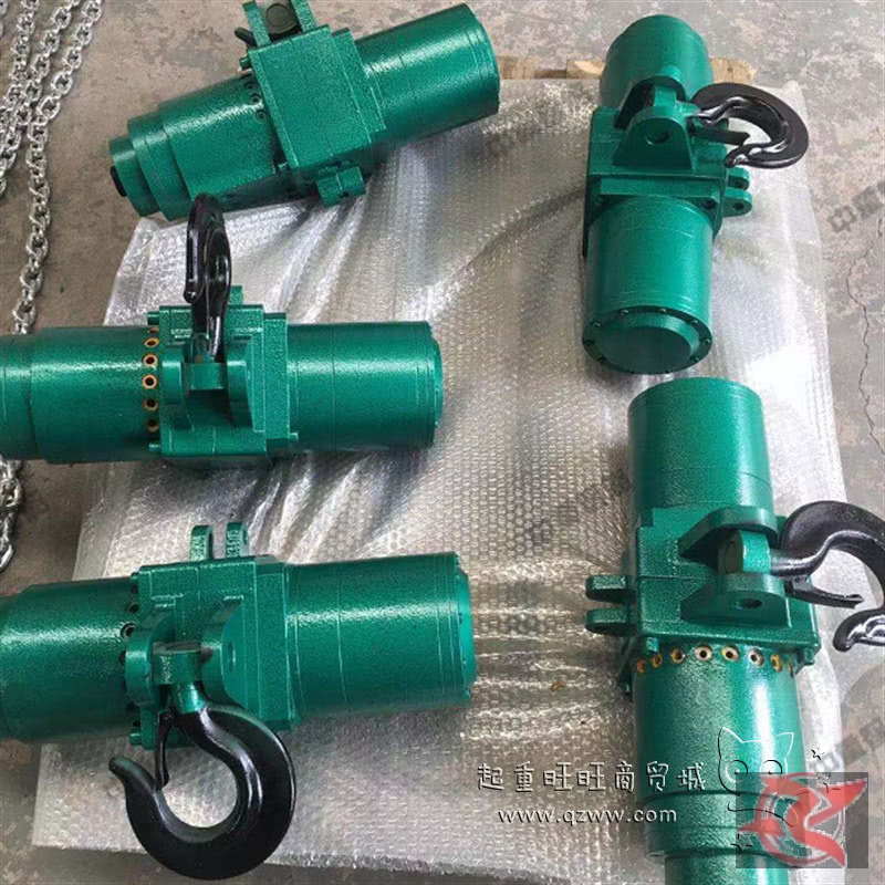
The HQ series pneumatic hoists cover load capacities from 1000kg to 5000kg. They are compact, lightweight, spark-free, shock-free, and safe and easy to use.
1. The pneumatic hoist is internationally recognized as the ideal lifting device and has been widely adopted in developed countries. It offers advantages that electric hoists cannot match:
a. Resistant to steam and high dust levels.
b. Compact and lightweight — weighing only 1/3 to 1/8 of an equivalent electric hoist.
Pneumatic Hoist Components:
- Hand Control Valve: Mainly composed of a handle, valve body, and push buttons. Operating the buttons opens the valve to connect the main control valve air circuit with the motor air circuit. It can also be operated by pull cord. Pulling the pendulum rotates it to open the valve, enabling infinitely variable-speed control.
- Main Control Valve: Mainly composed of left and right valve stems, connecting rods, and an air distribution plate. It switches the left and right air circuits to direct compressed air for forward and reverse rotation of the air motor.
- Air Motor: Mainly composed of a rotor, stator, front and rear end caps, and vanes. When the air distribution plate of the main control valve feeds compressed air into the motor, the vanes drive the rotor to spin at high speed.
- Suspension Assembly: Mainly composed of the top hook, suspension body, chain sprocket, chain, and bottom hook. Forward and reverse rotation of the chain sprocket drives the up-and-down motion.
- Reducer: Mainly composed of a housing and a set of planetary reduction gears. The high-speed shaft of the air motor feeds into the reduction mechanism, which reduces speed and multiplies torque for output to the load chain sprocket.
- Braking Mechanism: Mainly composed of a brake cone, brake ring, and pneumatic cylinder. The main control valve supplies air to the cylinder to separate the brake cone from the brake ring, releasing the brake.
- Interlock Mechanism: Mainly composed of a shaft, swing frame, and return spring. It provides collision protection at the upper and lower travel limits.
| Model | HQ02 | HQ03 | HQ04 | HQ05 | HQ06 | HQ07 | HQ08 | HQ09 | HQ10 | HQ11 | HQ12 | HQ13 | HQ14 | HQ15 | HQ16 |
| Lifting Capacity(t) | 0.125 | 0.25 | 0.5 | 1 | 2 | 3.2 | 5 | 10 | 15 | 20 | 25 | 30 | 40 | 50 | 60 |
| Lifting Speed(m/min) | 11 | 9 | 7 | 4 | 4 | 3 | 1.2 | 1.0 | 0.8 | 1.0 | 0.8 | 0.6 | 0.5 | ||
| motor power(ps) | 0.9 | 2.2 | 3.2 | 5.5 | 9 | 9 | 18 | 15 | 18.4 | ||||||
| Air Consumption(m3/min) | 1 | 1.86 | 2.56 | 3.6 | 6.8 | 13.5 | 16.5 | 20.5 | |||||||
| Working Air Pressure(Mpa) | ≥0.05 | ||||||||||||||
| Duty Classification | 100% | ||||||||||||||
| Dead Weight(Kg) | 16 | 18 | 28 | 32 | 44 | 58 | 126 | 245 | 320 | 978 | 1100 | 1250 | 1400 | 1500 | 1980 |
| Closed Height(mm) | 320 | 430 | 480 | 610 | 637 | 668 | 814 | 975 | 1100 | 1380 | 1450 | 1600 | 1780 | 1950 | |
| Recommended I-Beam | 10-18 | 16-18 | 16-22 | 18-28 | 28-36 | 36-50 | 50 | 50 | 50 | 50 | |||||
| Hoist Air Supply Hose Inner Diameter(mm) | φ12φ14φ16φ18φ22φ25φ32 | Pipe Diameter Based On Lifting Selection by Tonnage and Travel Distance |
| Trolley / Cross Travel Air Hose Inner Diameter(mm) | φ8φ10φ12φ13φ16 | |
| Control Air Hose Inner Diameter(mm) | φ4φ6φ8φ10φ12 |