

The Complete Guide to Crane Safety Protection: A Compilation of 15 Technical Articles on Rail Gnawing, Wind Protection, Lightning Protection, Limit Switches, and Collision Prevention
📌 Crane safety protection encompasses six core areas: rail gouging inspections, wind resistance and protection, lightning protection and grounding, limit switch calibration, collision protection, and AI safety monitoring.. This article compiles the highlights of 15 safety and technical articles from Krude Heavy Industry, covering everything from mechanical structural safety to electrical protection and intelligent monitoring, thereby forming a comprehensive safety protection technology system that complies with major safety standards such as GB/T 3811, GB/T 28264-2017, and TSG Q0008.
Troubleshooting and Track Adjustment for Overhead Cranes That Nibble the Rails
Rail gouging (flange wear) is one of the most common mechanical failures in overhead cranes, directly leading to premature wheel failure and damage to the main girder structure. Typical causes of rail gouging include excessive gauge deviation (the standard tolerance is less than 2 mm), diagonal misalignment of the wheels, and lateral bending of the main girder. Tracking issues should be investigated starting with the track foundation: first, measure the track gauge section by section using a laser rangefinder; then perform diagonal alignment; and finally, check for horizontal and vertical wheel misalignment. During repairs, priority should be given to adjusting the track while simultaneously adjusting the wheel position. Based on practical experience, Krued Heavy Industry has developed a comprehensive rail-biting remediation process that covers three major scenarios—flange wear, gauge deviation, and structural deformation—from detection and commissioning to preventive maintenance. Related references:The Complete Process for Troubleshooting and Adjusting Overhead Crane Rail Gouging。
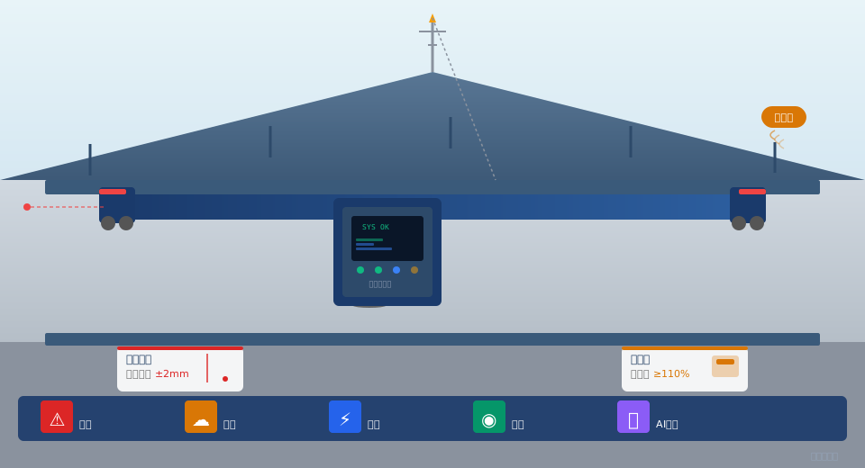
| Security Sector | Key Points | Key Criteria | Featured Articles |
|---|---|---|---|
| Track Gouging Inspection and Adjustment | Flange Wear Inspection, Gauge Deviation Correction, Structural Deformation Repair | GB/T 10183-2005 | 2 articles |
| Wind Protection and Wind Resistance System | Interlocking of Rail Clamps, Anchoring Devices, and Anemometers | GB/T 3811-2008 | 1 article |
| Lightning Protection and Grounding | TN-S Grounding, Equipotential Bonding, SPD Protection | GB 50057 | 1 article |
| Limit Switches and Safety Devices | Lifting Limit Switch, Travel Limit Switch, Overload Limiter | TSG Q0008 | 3 articles |
| Collision Protection | LiDAR, PLC Interlocks, Zone Limits | GB/T 28264-2017 | 2 articles |
| Security Monitoring and AI Vision | Intruder Detection, AI Visual Analysis, SIL 3 Architecture | GB/T 28264-2017 | 5 articles |
| Load Testing and Type Testing | Static/Dynamic Load Testing, Type Testing | GB/T 5905-2011 | 1 article |
Design and Interlocked Control of Wind-Resistant Systems
Gantry cranes operating outdoors must be equipped with reliable wind-resistant and wind-proof devices. The wind-proof system primarily consists of three core components: rail clamps (manual, electric, or hydraulic), anchoring devices, and an anemometer. The rail clamps automatically grip the rails when wind speed reaches a preset threshold (typically a Force 6 wind), while the anchoring devices secure the entire crane in place during high-wind alerts. The anemometer interfaces with the control cabinet to enable a full-chain response involving real-time wind speed monitoring, tiered alarms, automatic shutdown, and rail clamping. The design of the wind protection system must calculate wind loads in accordance with GB/T 3811 to determine the rated wind resistance capacity and the number of wind protection devices required. After installation, an integrated test must be conducted to verify that the time delay from the anemometer signal → PLC → track clamp activation is less than 2 seconds.
Lightning Protection Grounding and Electrical Safety Design
The crane’s lightning protection system uses a TN-S grounding configuration, strictly separating the power supply neutral point from the protective grounding. Outdoor crane tracks must be grounded, with a grounding resistance of less than 4 Ω. In the electrical system, equipotential bonding connects all exposed metal parts into a single system, and SPDs (surge protective devices) are installed at the power and signal line entry points to prevent lightning surges from entering. The lightning protection grounding system must undergo regular testing of grounding resistance and SPD operational status to ensure reliable operation during the thunderstorm season. A comprehensive lightning protection solution covers three key aspects: direct lightning strike protection, induced lightning protection, and the grounding system.
Procedures for Commissioning Limit Switches and Safety Devices
Limit switches are the first line of defense for safe crane operation. Hoist limit switches (weight-driven, screw-type, or electronic) automatically cut off the hoisting circuit when the hook reaches the upper limit position; travel limit switches trigger deceleration and stopping when the main or trolley travel reaches either end of the track; and overload limiters emit audible and visual alarms and cut off hoisting when the lifted weight exceeds the rated load. Each type of limit switch has strict commissioning procedures: the operating point of the hoisting limit switch must allow for at least 2 to 3 turns of slack wire rope on the drum; the buffer distance for the travel limit switch must be no less than 500 mm; and the set value of the overload limiter must not exceed 110% of the rated load.
Collision Protection and Multi-Vehicle Cooperative Safety
In scenarios involving multiple cranes operating across the same span, the collision prevention system prevents collisions between adjacent cranes. The system architecture consists of three levels: LiDAR distance sensors, PLC interlock logic, and zone limit switches. The LiDAR measures the distance between the two cranes in real time (with an accuracy of ±5 cm); when the distance falls below the safety threshold, a deceleration signal is triggered; PLC interlock logic ensures that two vehicles on the same track do not simultaneously enter the same conflict zone; zone limit switches, installed at key points along the track, serve as the final mechanical safeguard. In addition to collision protection, multi-vehicle coordination must also address scheduling protocols and safety interlock logic during cross-operation scenarios.
Security Monitoring and AI-Powered Visual Protection
The GB/T 28264 standard requires lifting machinery to be equipped with a safety monitoring and management system that collects operational parameters—such as load capacity, lifting height, travel distance, and wind speed—in real time, and includes functions for out-of-limit alarms and event logging. Building on this, the AI-powered visual safety monitoring system uses high-definition cameras deployed in the lifting area and deep learning algorithms to identify hazardous conditions in real time, such as personnel intrusion, abnormal swaying of the load, and deviation in the lifting device’s orientation. The SIL 3 architecture of the safety control system employs a dual-brake redundancy design, with the main and auxiliary brakes controlled independently; any single-point failure does not affect safety functions. The PLC safety logic is programmed according to the PROFiSafe protocol, with a fault response time of less than 100 ms. Related references:Design and Application of a Safety Monitoring and Management System for Overhead Cranes。
Overview of the Overhead Crane Safety Monitoring and Management System
Frequently Asked Questions
Q: Which national standards cover crane safety protection?
Answer: The main standards include GB/T 3811 (Code for Design of Cranes), GB/T 28264-2017 (Safety Monitoring and Management System), TSG Q0008 (Technical Regulations for Safety of Lifting Machinery), GB/T 5905-2011 (Specifications for Load Testing), and GB 50057 (Code for Lightning Protection Design). Each standard addresses a different aspect of safety protection.
Q: How often should rail gouging be inspected?
Answer: It is recommended to conduct a visual inspection of the track gauge and flange wear once a month, measure track gauge accuracy with a laser rangefinder once a quarter (with a standard tolerance of less than 2 mm), and perform a comprehensive inspection of wheel misalignment and main girder camber once a year. For cranes in heavy use, visual inspections may be increased to once every two weeks.
Q: What are the key considerations when selecting a wind-resistant rail clamp?
Answer: The wind resistance capacity of the rail clamp must exceed 110% of the wind load on the crane’s wind-exposed area, as calculated and determined in accordance with GB/T 3811. When selecting a model, you must also consider the rail type (P43/P50/QU70, etc.), clamping method (manual/electric/hydraulic), response time (less than 2 seconds for electric, less than 1 second for hydraulic), and installation space. Krude Heavy Industry has extensive engineering experience in the integration of wind protection systems.
Q: What is the detection accuracy of the AI-powered visual safety monitoring system?
Answer: In personnel intrusion detection scenarios, the deep learning-based AI vision system achieves a recognition accuracy of 99.5% or higher, with a latency of less than 200 ms from image capture to alarm triggering. The system supports multi-target tracking and hazard zone delineation, and detection strategies can be flexibly adjusted based on on-site operating conditions. Combined with a SIL 3 safety PLC architecture, it meets the highest level of functional safety requirements.
