

Overhead Crane Simulation Calibration: Kinematic, Dynamic & FEA
Calibrating the parameters of an overhead crane simulation model is the critical step that takes a Digital Twin from "looks good" to "works well." A properly calibrated model keeps simulation error within 5%, while an uncalibrated one can drift as high as 40%. This article breaks down the calibration methods, tool selection, and convergence criteria for four parameter categories: kinematics, dynamics, FEA, and rigid-flexible coupling.
The first two articles covered the overall Digital Twin architecture and the AAS data model—now we dive into simulation.
The key difference between a Digital Twin and a standard 3D monitoring system is that the twin can actually compute. But whether those computations are accurate depends less on how expensive the simulation software is and more on how meticulously the model parameters are calibrated. Take the same overhead crane model: with proper calibration, simulation error stays under 5%; with arbitrarily entered parameters, it can balloon to 50%. We ran a side-by-side comparison—the same crane, calibrated model error under 5%, factory-default parameters error close to 40%. The gap is enormous.
This article walks through the parameter calibration methods for overhead crane simulation models—kinematics, dynamics, FEA, and rigid-flexible coupling—covering how to calibrate each type, which tools to use, and what convergence criteria to apply.
| Calibration Parameter | measurement method | Calibrationmethod | typical error source | convergence criterion |
|---|---|---|---|---|
| Crane Bridge / Long Travel Positioning Accuracy | laser tracker | multi-point measurementvs Encoderfitting | wheel slippage, Crane Railunevenness | ±10mm |
| Trolley Positioning Accuracy | Laser Distance Sensor / Laser Rangefinder | same Crane Bridge / Long Travelmethod | Gearclearance, Braking Deviation | ±5mm |
| Lifting Height Accuracy | Encoder+laser | Wire Rope Pulley Ratio Coefficient Calibration | rope Elasticityelongation, Drumerror | ±20mm |
| joint dynamic following | high-speed camera/IMU | step response transfer function | adddeceleration time, PIDParameter | position error<5% |
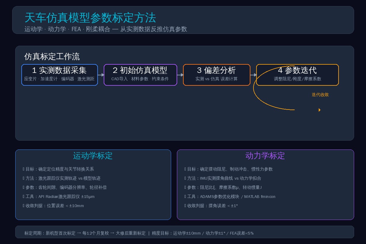
Calibration Fundamentals for Crane Simulation Models
Simulation calibration boils down to one goal: making the simulation output match physical-world measurements.
The standard process follows four steps:
- Measured data collection: Place sensors at critical crane locations to capture real motion and force data as the reference baseline.
- Initial simulation model: Build a first-pass model based on CAD design and material parameters, then run it.
- Deviation analysis: Overlay simulation output against measured data and calculate the error.
- Parameter iteration: Adjust tunable model parameters—friction coefficient, damping ratio, stiffness coefficient, etc.—until the error falls within an acceptable range.
Calibration is not a one-time event. The standard cadence is: initial calibration for new models, recalibration every 12 months, and recalibration after any major overhaul.
Kinematic Model Calibration: Key Parameters
Kinematic calibration addresses whether the crane in the model moves accurately. The primary calibration parameters include:
| Parameter | physical meaning | Calibrationmethod | typical initial value | Calibrationpost-range |
|---|---|---|---|---|
| damping ratioξ | Wire Ropeswing decay | logarithmic decrement of free decay | 0.01~0.05 | 0.015~0.035 |
| friction Coefficientμ | wheel/Crane Railrolling friction | no-load coasting distance Testing | 0.01~0.03 | 0.015~0.025 |
| moment of inertia J | Motor+Coupling+Drum | CADtypical initial value+add Decelerationcorrection | according to CAD | CAD×1.05~1.15 |
| Stiffness Coefficientk | Wire Ropetension Stiffness | static loadforce-displacement fitting | EA/L | theoretical value×0.85~0.95 |
| Brakeresponse | Brakingsignal to Brake applicationin position | high-speed camera+Currentclamp | manufacturer | measured value±15% |
This includes:
Recommended Tools: API Radian laser tracker (accuracy ±15μm/m), FARO Focus laser scanner. For tighter budgets, a high-precision RTK-GNSS + IMU combination is a viable alternative—slightly lower accuracy, but at roughly one-fifth the cost of a laser tracker.
Dynamic Model Calibration
Dynamic calibration is the most critical—and most challenging—step in simulation. It determines whether braking distance calculations are accurate, whether wire rope swing angles are correct, and whether structural impact forces reflect reality.
3.1 Key Calibration Parameters
The core parameters for dynamic calibration include: wire rope damping ratio ξ, drag coefficient Cd, friction pair damping c, acceleration/deceleration time constant τ, and hoisting dynamic coefficient φ. These parameters directly govern how accurately the overhead crane responds during start-up, speed changes, and braking—and they influence key simulation indicators such as braking distance, load swing angle, and structural impact force.
The wire rope damping ratio ξ is the most sensitive parameter—an error of just 0.01 can shift swing angle predictions by 3–5°, and it also demands the most calibration effort. For indoor cranes, the drag coefficient Cd can be taken as 0.8–1.0; for outdoor cranes, it should be adjusted to 1.2–1.5 based on measured wind speeds. The acceleration/deceleration time constant τ directly affects start/stop impact forces and must be calibrated jointly from VFD parameters and measured current curves.
3.2 Swing Parameter Calibration—Step-by-Step Procedure
Wire rope swing is the most critical and error-prone aspect of overhead crane dynamic simulation. The calibration procedure is as follows:
- Lift 50%–100% of the rated load, keeping the load approximately 1 meter above the ground.
- Apply a short-pulse crane bridge movement command (emergency stop) to induce free swinging of the load.
- Position a high-speed camera (240 fps or higher) directly below the hook to record the swing motion.
- Extract the load's swing angle time-history curves in the X/Y directions from the video.
- Calculate the damping ratio using the logarithmic decrement method: ξ = (1/(2πn)) × ln(θ₁/θₙ₊₁), where θ₁ is the swing angle of the first cycle and θₙ₊₁ is the swing angle of the (n+1)th cycle.
- Input the measured damping ratio into the dynamic model, re-run the simulation under the same operating conditions, and compare the swing angle curves.
- Adjust the drag coefficient and friction pair damping in the model until the peak swing angle error between simulation and measurement is <±1°.
In general, the wire rope damping ratio ξ falls between 0.015 and 0.035. Values below 0.015 indicate the model is too "slippery," while values above 0.035 suggest the damping assumption is too high.
FEA Finite Element Model Calibration
4.1 Static Calibration
The goal of FEA model calibration is to align simulated stress contours with measured strain data. The procedure:
- Attach strain gauges at critical sections of the main girder (mid-span bottom flange plate, end carriage connections, weld seam areas).
- Apply stepwise loading: 25%, 50%, 75%, 100%, 125% of rated load.
- Record strain gauge readings after each load step stabilizes, then convert to stress values.
- Apply the same loads in the FEA model and extract simulated stress values at corresponding nodes.
- Calculate relative error: (simulated stress – measured stress) / measured stress × 100%.
- If error exceeds 10%, check boundary conditions (constraint correctness), mesh density (whether weld seam areas are refined), and material parameters (whether E and ν are accurate).
4.2 Modal Calibration
Dynamic simulation requires accurate modal parameters. The method:
- Place 5–8 acceleration sensors on the main girder.
- Excite the structure using impact hammer strikes or the transient excitation from crane start/stop operations.
- Capture vibration signals and apply FFT to obtain the first 10 natural frequencies and mode shapes.
- Compare against FEA modal analysis results, focusing primarily on the 1st vertical bending frequency (A6/A7 class cranes require ≥2 Hz).
- If deviation exceeds 5%, adjust mass distribution or boundary stiffness in the FEA model.
Rigid-Flexible Coupling Calibration
The biggest pitfall in overhead crane simulation—the wire rope. It behaves as a flexible body (stretching, bending, torsion) while connecting to a rigid load. A purely rigid-body model produces unreliable results, while a fully flexible model is computationally too slow. Engineering practice uses a discretized rope model: the wire rope is divided into N segments of rigid bodies connected by spring-damper elements.
Key calibration parameters:
- Number of discrete segments N: Higher N improves simulation accuracy but increases computation time. Rule of thumb: for lifting height ≤16 m, use N=20; for height >16 m, use N=30.
- Rope stiffness k: Theoretical value k=EA/L, but due to the stranded construction of wire rope, the elastic modulus is 15%–20% lower than solid steel. After calibration, use 0.85× the theoretical value.
- Rope damping c: Depends on wire rope lubrication condition and construction method. Fit from measured free-decay curves; typical values range c=0.5–2.0 N·s/mm.
- Pulley contact friction: Friction hysteresis occurs as the wire rope winds around the drum. After calibration, use μ=0.08–0.12.
Calibration Tools and Process Summary
The tools, duration, accuracy targets, and difficulty levels for different calibration types are compared below:
| Calibrationtype | primary tool | Calibrationperiod | Accuracytarget | difficulty |
|---|---|---|---|---|
| kinematics | laser tracker/Encoder | first time+annually | ±10mm | |
| dynamics | IMU/high-speed camera/Currentclamp | first time+annually+Overhaulafter | swing angle±1° | |
| FEAstatic | strain gauge/data acquisition unit | first time | stress error<10% | |
| FEAmodal | accelerometer/impact hammer/FFT | first time+Overhaulafter | Frequency Deviation<5% | |
| rigid-flexible coupling | high-speed camera+Recur Dyn | first time | rope force error<8% |
7 Common Calibration Pitfalls to Avoid
- Copying material parameters straight from the manual: The Elastic Modulus of Q355B (≈S355JR) is listed as 206GPa in handbooks, but differences in the Rolled direction of the Steel Plate can cause anisotropy, with deviations up to 5%. For critical projects, it's recommended to take samples for a tensile test.
- Over-idealized constraint conditions: Applying a "fixed constraint" to the bottom of the End Carriage is the most common shortcut in FEA. In reality, the Crane Rail has elasticity, and the Runway Beam also deforms. The correct approach is to replace rigid fixed constraints with spring-damper constraints, using the measured stiffness of the rail support for the spring constant.
- Mesh not fine enough: A model with 500,000 elements can show a 30% difference in maximum stress at the Weld Seam compared to a 50,000-element model. If you're concerned about local stress, the mesh must be refined to below 10mm.
- Calibrating for only one load case: Calibrating only for the rated load can lead to overfitting. It's recommended to calibrate for at least three load cases (empty, 50% rated, 100% rated) to ensure the model is accurate across its entire working range.
Final Thoughts: From Simulation to True Digital Twin
Calibrating simulation model parameters is the critical step that takes a Digital Twin from looking good to being genuinely useful. A simulation without proper calibration is just a 3D animation. With calibrated parameters, it becomes a true Digital Twin.
For a deeper dive into related performance topics, see our article on Edge-Side Real-Time Rendering Optimization, which covers WebGL rendering optimization, model decimation strategies, and data compression for transmission.
Related Standard
Frequently Asked Questions
Q: What sensors and equipment are needed for calibration?
A: Kinematic calibration requires a laser tracker (accuracy ±15μm/m). An RTK-GNSS+IMU system can be used as a lower-cost alternative at about 1/5 of the price. Dynamic calibration requires a high-speed camera (240fps or higher) and Acceleration Sensors. FEA static calibration requires strain gauges and a data acquisition system. The total investment for a full setup is approximately $12,000 to $22,000.
Q: How long does a calibration take?
A: An initial full calibration (kinematic + dynamic + FEA) typically takes 2-3 working days. The FEA static calibration, which requires stepped load testing, is the most time-consuming part. An annual re-calibration takes only half a day, mainly to verify that key parameters haven't drifted. A full re-calibration after an Overhaul takes about 1 working day.
Q: What happens if I use the simulation model without calibration?
A: We ran a comparative test on the same overhead crane: the calibrated model had a simulation error of less than 5%, while the model using factory default parameters had an error of nearly 40%. The uncalibrated model was particularly unreliable for brake distance calculations and wire rope swing angle predictions. In short, an uncalibrated simulation is just a 3D animation.
