

FPSO Dual Crane Lifting Load Distribution & Stability Check
FPSO topside module weights range from several hundred to several thousand metric tons, making single-crane lifts impractical in most cases. Dual-crane (or even triple-crane) coordinated lifting is therefore mandatory. The core technical challenge in dual-crane lifting is uneven load distribution—the combined effects of wire rope stiffness differences, slew angle deviation, and vessel inclination can push actual load sharing up to ±20% or more off the design values. Precise calculation and real-time monitoring are essential to ensure safety.
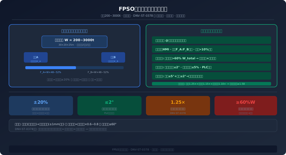
FPSO (Floating Production Storage and Offloading) topside modules represent one of the most demanding lifting scenarios in offshore engineering. Individual modules—such as oil/gas separation units, compressor packages, or power generation modules—typically weigh between 200 and 3,000 metric tons, with physical dimensions reaching 30 m × 20 m × 25 m. During construction and integration, shipyards use large portal cranes or floating cranes to transport these massive structures from the quayside prefabrication area to their designated positions on the FPSO hull. The alignment tolerance for flange bolt holes is ≤5 mm.
Load distribution calculations and stability analysis for dual-crane lifts follow the load combination principles of ISO 4301, while synchronization control accuracy references the additional safety factor requirements for multi-crane operations specified in DNV-ST-0378.
When a module's weight exceeds a single crane's rated load—or when the module's dimensions are too large or its center of gravity is severely eccentric, making single-point lifting unable to maintain levelness—dual-crane lifting becomes necessary. Two cranes, each with its own hook and wire rope, simultaneously lift the same module. This article focuses on the primary risk in dual-crane lifting—uneven load distribution—and covers both calculation methods and mitigation strategies.
Load Distribution Calculation for Dual-Crane Lifts
In an ideal scenario, load distribution between two cranes is determined by the module's center of gravity relative to the two lift points. The loads carried by each crane, F₁ and F₂, follow the lever principle: F₁/F₂ = L₂/L₁, where L₁ and L₂ are the horizontal distances from the center of gravity to lift points 1 and 2, respectively. For example, with an 800 t module where the center of gravity is 8 m from Crane A and 12 m from Crane B, Crane A carries F_A = 800 × 12/(8+12) = 480 t, and Crane B carries F_B = 800 × 8/20 = 320 t.
However, this is only the starting point of the calculation—three real-world factors cause actual load distribution to deviate from design values. The first is wire rope elasticity variation: even when both cranes use wire ropes of identical specification (e.g., 52 mm diameter, 1960 grade), the actual elastic modulus can vary by ±5% due to manufacturing batch differences and micro-plastic elongation from prior service. Taking the 800 t module with a 4-part reeving as an example, the unloaded rope length is approximately 80 m. Under a 480 t load, elastic elongation ΔL = F×L/(E×A) ≈ 480×10⁴×80/(1.05×10¹¹×4×π×0.026²) ≈ 0.21 m. If the two cranes' wire ropes have a 5% elastic modulus deviation, the elongation difference is approximately 10 mm—seemingly negligible, but during the module alignment phase (requiring ±5 mm accuracy), this is enough to cause one hook to "steal" load (the crane whose hook contacts the flange first takes on a disproportionate share of the load).
Dual-Crane Synchronization—Slew Angle and Vessel Inclination Effects
The second critical factor is hoisting speed synchronization deviation between the two cranes. Even when both winch speed commands are identical (e.g., 0.5 m/min), differences in hydraulic system response, winch gearbox backlash, and multi-layer rope winding radius on the drum can cause actual hook speeds to deviate by ±3% to 5%. With a total lifting height of 15 m, a 3% speed deviation produces approximately 450 mm of height difference at the top of the lift—far exceeding the allowable module levelness tolerance.
The solution is to install inclination sensors at the four corners of the module (e.g., Pepperl+Fuchs INX360D-F99-I2E2-V15, resolution 0.01°). Real-time tilt angles are transmitted wirelessly (e.g., Wi-Fi 802.11n or LoRa 868 MHz) to both cranes' PLC controllers. The PLC calculates the height correction corresponding to the tilt angle (for a 20 m long module, 0.1° of tilt ≈ 35 mm height difference) and dynamically adjusts winch speeds—reducing speed 10% to 20% on the high side and increasing speed 10% to 20% on the low side—maintaining module inclination within ±0.05°. This closed-loop inclination synchronization delivers approximately 10× greater accuracy than traditional open-loop speed synchronization.
The third critical factor is the crane stalk's (floating crane's) own inclination. When dual-crane lifting is performed from floating cranes, wave and wind-induced hull trim/heel causes the boom tip's actual spatial position to deviate from GPS-derived values—1° of hull heel produces approximately 870 mm of horizontal offset and 15 mm of vertical offset at a 50 m boom tip. Therefore, when using floating cranes for dual lifts, each crane must be equipped with a motion reference unit (MRU). The MRU feeds six-degree-of-freedom vessel motion data (surge/sway/heave/roll/pitch/yaw) in real time to the crane control system, which uses coordinate transformation to convert hook target positions from the vessel coordinate system to the earth-fixed coordinate system, canceling out vessel motion interference on hook positioning.
Real-Time Load Monitoring and Overload Protection
The most dangerous scenario in dual-crane lifting is "silent overload"—because the module does not drop and the crane does not alarm, operators may be completely unaware that one crane is already overloaded by 10% to 15%. For this reason, dual-crane lifts must be equipped with an independent load monitoring system (LMS) rather than relying solely on the crane's built-in load moment limiter.
A typical LMS configuration: load pin type weighing sensors (e.g., custom Strainsert units, 0–600 t range, ±0.5% FS accuracy) are installed at the dead-end anchor points of each crane's wire rope. The 4–20 mA signals pass through signal conditioning modules for filtering and noise reduction, then transmit via Modbus TCP to a central data acquisition unit (DAQ). The HMI displays real-time load distribution percentages for both cranes numerically and as bar charts. Two alarm levels are configured: when a crane's actual load exceeds 115% of its calculated share, a yellow warning triggers (lifting may continue, but operators are alerted to check synchronization status); at 125%, a red alarm triggers and hoisting speed automatically reduces to 10% of rated speed; at 130%, the safety PLC initiates an emergency stop. The entire LMS must be independent of the crane's own PLC (to prevent a single point of failure from disabling both load monitoring and crane control simultaneously) and must be backed by a UPS with a minimum 30-minute battery runtime.
| Detection Parameter | Sensor Type | Accuracy | Alarm Threshold |
|---|---|---|---|
| Crane ALoad | Pin-type Load Cell / Weighing Sensor | ±0.5% FS | >115%Yellow/>125%Red/>130%Stop |
| Crane BLoad | Pin-type Load Cell / Weighing Sensor | ±0.5% FS | >115%Yellow/>125%Red/>130%Stop |
| Moduleabrasion-resistant Degrees | Dual-axis Inclination Sensor | ±0.01° | >0.1°Pre-warning/>0.3°Stop |
| Double Hook Height Difference | Laser Distance Sensor / Laser Rangefinder | ±1mm | >20mm Pre-warning/>50mm Stop |
| Floating Crane Hull Attitude | MRUSix-axis Sensor | ±0.01° Roll | >2°Pre-warning/>5°Stop |
| Wind Speed | Ultrasonic Anemometer | ±0.5m/s | >12m/s Pre-warning/>15m/s Stop |
| Module Weight Range | Recommended Coordination Scheme | Rigging Configuration | Synchronization Accuracy Requirement |
|---|---|---|---|
| 200~500t | Twin Crane Lifting 60/40Distribution | Wire Rope+Spreader Beam | ±50mm |
| 500~1000t | Twin Crane Lifting 55/45Distribution | Wire Rope+Hydraulic Balancing System | ±30mm |
| 1000~2000t | Triple Crane Lifting 40/35/25 | Wire Rope+Hydraulic Synchronization Cylinder | ±20mm |
| >2000t | Twin Floating Crane Combination Lifting | Wire Rope+AHCCompensation | ±10mm |
Rigging Design for Dual-Crane Lifts: Spreader Beams & Hydraulic Synchronizing Cylinders
For modules that are slender (length-to-width ratio >3:1) or have an uncertain center-of-gravity height, even a precise load distribution calculation may not prevent tipping during a direct wire-rope lift — because the assumed center of gravity can deviate from the actual one. In such cases, a spreader beam or a hydraulic synchronizing cylinder system must be installed between the hooks and the module.
A spreader beam converts the concentrated loads from two hooks into a uniformly distributed load along the beam length. The beam is connected to the crane hooks via wire ropes on top and to the module through multiple lifting points underneath, allowing the module to self-level during the lift — much like a balance scale. The hydraulic synchronizing cylinder system is more advanced: four or eight hydraulic cylinders (connected via hoses to a central hydraulic power unit, HPU) are mounted at the module corners. Each cylinder is equipped with a displacement sensor (accuracy ±0.1mm), and a PLC controls the extension of each cylinder through servo valves, keeping the module level throughout the hoisting process (tilt <0.05°). This system automatically compensates for height differences of up to <200mm between the two crane hooks — eliminating the need for operators to manually adjust the winches of both cranes. This is especially critical in offshore lifting scenarios where sea conditions cause continuous hook-height fluctuations.
Frequently Asked Questions
Q: What happens if one crane fails suddenly during a dual-crane lift? Can the other crane handle the full load alone?
A: No, it cannot. A dual-crane lift is never designed on the assumption that one crane can take the full load if the other fails — if that risk exists, the module should not be lifted with two cranes at all; a larger single crane should be used instead. The safety measures in practice are: ① Both cranes are equipped with cross-communication (heartbeat signal every 50ms). If either crane detects a communication loss or a PLC fault signal from the other, it immediately triggers a "synchronized deceleration-stop" sequence — both cranes slow to 10% of rated speed, hold the load for 2 seconds (to confirm module stability), then come to a full stop with brakes applied. ② A third standby crane (auxiliary crane with a lifting capacity ≥30% of either main crane) is positioned on site. Within 5–10 minutes, it is rigged to auxiliary lifting points, and the failed crane's load is slowly transferred. If no standby crane is available, the module is carefully lowered onto a pre-positioned temporary support structure (typically a steel lattice frame placed at the planned landing location).
Q: Why use two cranes for FPSO module lifts instead of one larger crane?
A: Three main constraints drive this decision. First, existing yard equipment capability — not every shipyard has a super-heavy portal crane above 2,000t (for example, ZPMC's "Honghai" 22,000t gantry crane is the only one of its kind in the world). Most yards have a maximum lifting capacity in the 600–1,200t range, so modules exceeding this weight must be lifted with two cranes. Second, economics — the daily charter rate for ultra-heavy floating cranes (such as the Heerema Thialf at 14,200t or the Saipem 7000) runs as high as $500k–$1M per day. Using existing equipment with a dual-crane lift dramatically reduces lifting costs. Third, module design itself is evolving — more FPSO projects are adopting modular construction strategies, splitting oversized modules into 2–3 sub-modules that are built and lifted separately, then joined on the hull. This approach fundamentally eliminates the need for a single ultra-heavy lift.
Q: How do you compensate for uneven elastic elongation of wire ropes in a dual-crane lift?
A: If both cranes use identical wire rope specifications and the same pulley ratio, the difference in elastic elongation is typically <15mm — a magnitude that can be handled during the module mating phase through a "micro-lowering" procedure: when the module is approximately 100mm above the flange face, both cranes switch to "Inching Mode" — each press of the control grip lowers the hook by 1–3mm. The two cranes are operated alternately so that all four corners of the module contact the flange face simultaneously. If the module is equipped with a hydraulic synchronizing cylinder system, the compensation is handled automatically by the hydraulic system. For extremely tight alignment requirements (e.g., subsea manifold flange connections with a permissible deviation of ±2mm), laser trackers (such as the Leica AT403 or API Radian) can be mounted at the module corners to measure the module's six-degree-of-freedom spatial deviation from the target position in real time, feeding the data back to both crane controllers for closed-loop compensation.
Q: What inspections and approvals are required before a dual-crane lift?
A: Per DNV-OS-H205 and API RP 2D, the following documentation must be completed before a tandem crane lift: ① A detailed lifting procedure, including a load distribution calculation sheet (stamped by a registered structural engineer), rigging configuration drawings, a crane layout plan (with crane positioning coordinates and working radius for each crane lighter), and a description of the synchronization control logic between the two cranes; ② A risk analysis report (HAZID/HAZOP) identifying all potential failure modes and defining mitigation measures; ③ A crane communication test report verifying the effectiveness of heartbeat signals and the emergency shutdown interlock; ④ Qualification certificates for crane operators and signal persons (OPITO- or API-recognized crane operator certificates required); ⑤ Approval from a third-party Marine Warranty Survey (MWS) — a mandatory requirement for insurance coverage on most offshore projects. All documents must be submitted to the MWS at least 14 days prior to the hoisting operation. Any lift performed without this approval will void insurance coverage in the event of an incident.
Kelude Heavy Industry provides engineering support for offshore module hoisting projects, including tandem/multi-crane lifting plan design, load monitoring system integration, and Marine Warranty Survey technical assistance. Contact our engineering team for project-specific solutions.
