

Electric Hoist Brake Failure Troubleshooting: 7 Causes & Fixes
📋 Quick Diagnostic Summary
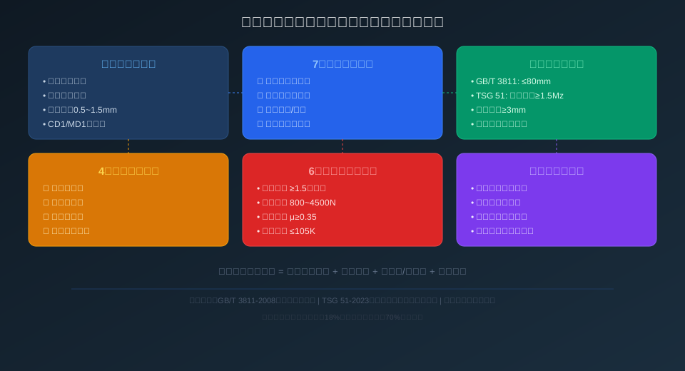
Electric hoist brake failure typically presents as load creep under full load, weak braking response, and excessive braking distance. Root causes include worn brake linings (thickness <3mm), fatigue fracture of the brake spring, oil contamination on the brake wheel surface, excessive clearance from a loosened lock nut, and a seized conical rotor that fails to return. Per ISO 4301 Crane Design Standard, the allowable load drop during a 10-minute hold at rated load is ≤80mm; TSG 51-2023 Crane Safety Technical Supervision Regulation requires braking torque to be at least 1.5 times the rated load torque. Kelude's technical service team reports that brake faults account for approximately 18% of all electric hoist failures, with 60% of those preventable through regular brake gap adjustment and lining replacement.
Common Symptoms of Electric Hoist Brake Failure
The electric hoist brake is a critical safety component in lifting operations. When it fails, the consequences range from dropped loads to serious personal injury. Based on Kelude's after-sales maintenance records, brake failure typically manifests in three distinct operating conditions:
① Load creep during hoist hold under rated load. Under normal conditions, the load drop during a 10-minute hold at rated load should not exceed 80mm (per ISO 4301 Crane Design Standard, Section 7.4.3). When brake linings wear to a thickness of <3mm or the brake spring preload drops, the load creep can exceed 200mm, creating a serious dropped-load hazard.
② Excessive braking distance during power-off braking. A conical-rotor brake motor should complete brake application within 0.3 seconds of power loss. When the conical rotor seizes against the stator cone, the release mechanism corrodes, or the brake disc face runout exceeds tolerance, the braking response time extends beyond 1 second, significantly increasing load travel.
③ Brake fails to release during no-load operation. When the brake does not disengage after power-on, the motor stalls with a characteristic hum and current spikes, tripping the overcurrent protection within 5 seconds. Common causes include brake gap set too tight (<0.2mm), a broken release spring, or a burned-out electromagnetic coil.
Brake Drop Standards: ISO 4301 and TSG 51 Inspection Requirements
ISO 4301 Crane Design Standard, Section 7.4.3, specifies that the hoisting mechanism brake must hold the rated load reliably, with a permissible drop of no more than 1/100 of the lifting speed during a 10-minute hold (typically equivalent to ≤80mm). The brake must also meet static braking requirements at 1.5 times rated load and dynamic braking requirements at 1.1 times rated load.
TSG 51-2023 Crane Safety Technical Supervision Regulation, Section 2.8, imposes stricter safety supervision requirements: the hoisting mechanism must be equipped with a normally closed brake, with a braking torque safety factor ≥1.5 (the ratio of braking torque to rated hoisting torque). Section 3.5 further mandates that brake components—linings, springs, and brake wheels—be included as mandatory inspection items during every periodic inspection, conducted at 2-year intervals.
GB/T 28264-2012 Safety Monitoring and Management System, Section 5.2.3, requires that for cranes with a lifting capacity of ≥10t, the brake be fitted with open/close status monitoring sensors wired into the safety monitoring system. In the event of a brake anomaly, the system must automatically cut power to the hoisting mechanism and trigger an audible and visual alarm. Kelude's full range of electric hoists can be equipped with an optional brake status monitoring module to meet compliance requirements.
Conical-Rotor Brake Motor: Operating Principle and 7 Failure Modes
The core of the electric hoist braking system is the conical-rotor brake motor. Its operating principle: when energized, the stator magnetic field generates axial magnetic pull that overcomes the brake spring pressure, drawing the conical rotor into the stator cone bore and disengaging the brake disc from the linings, allowing the motor to rotate. When power is cut, the magnetic pull disappears, the brake spring pushes the rotor axially outward, and the brake disc presses against the linings to apply the brake.
According to Kelude's after-sales maintenance database, brake failures can be classified into the following 7 categories by failure mechanism:
① Excessive brake lining wear (32% of cases). Linings are made of asbestos-based or semi-metallic friction material with a typical service life of 5,000–8,000 braking cycles. When lining thickness wears down to <3mm, the reduced friction area results in insufficient braking torque and immediate replacement is required. ISO 4301 specifies replacement when remaining lining thickness falls below 50% of the original.
② Brake spring fatigue fracture (18% of cases). The brake spring is a cylindrical helical compression spring made of 60Si2Mn spring steel, rated for approximately 500,000 duty cycles. Under prolonged high-frequency use, the spring undergoes stress relaxation, with preload dropping 30%–50%, leading to insufficient braking torque. Fractures typically occur at the end-coil transition zone, with the fracture surface showing characteristic fatigue striations.
③ Oil contamination on the brake wheel/disc surface (15% of cases). Aging gearbox oil seals allow gear oil to seep along the motor shaft into the brake chamber, forming an oil film on the brake disc working surface. The friction coefficient drops sharply from a normal 0.35–0.45 to 0.05–0.10, reducing braking torque by over 80%. This issue is particularly prevalent in long-travel hoists with a lifting height of ≥12m.
④ Seized conical rotor (12% of cases). After extended motor operation, the air gap between the conical rotor and stator cone (standard 0.25–0.40mm) becomes uneven due to bearing wear. The rotor develops eccentric wear and fails to eject smoothly on power-off, leaving the brake in a partially released state. Disassembly reveals visible single-sided wear marks on the cone surface.
⑤ Loosened lock nut (10% of cases). The brake gap adjustment lock nut works loose under prolonged vibration, expanding the brake gap from the standard 0.5–1.5mm to 2–3mm or more. The increased axial travel reduces brake spring preload. Maintenance personnel should re-measure with a feeler gauge and re-torque the lock nut.
⑥ Electromagnetic release failure (8% of cases). Inter-turn short circuits in the release solenoid coil reduce the holding force, preventing full brake release. The motor then starts under brake application, drawing 6–8 times the rated current. The coil should be replaced when insulation resistance drops below 0.5MΩ.
⑦ Brake disc face runout out of tolerance (5% of cases). When the brake disc face runout exceeds 0.08mm after machining or installation, the linings make uneven contact, reducing the effective friction area and accelerating localized wear from overheating. Reinstallation requires dial indicator correction, with runout controlled to <0.05mm.
Brake Failure Diagnosis: Parameter Reference Table
| Failure Type | Fault Symptom | Diagnosis Parameter/Threshold |
|---|---|---|
| Braking Disc Wear | Drop Distance>80mm, Braking Present Abnormal noise | Thickness<3mm(Standard≥6mm New Component) |
| Spring Fatigue/Fracture | Braking Force Gradually Lowering, Normal at No-Load, Drop Under Load | Free Length Reduction≥5%, Preload< Rated80% |
| Brake wheel Oil Contamination | Drop Accompanied by Slight Slipping Sensation, Braking Polished Surface | Friction Coefficientμ<0.15(Standardμ≥0.35) |
| Conical Rotor Seizure | Brake Delay After Power-Off0.5~2Seconds | Air Gap Deviation>0.15mm(Standard0.25~0.40mm) |
| Lock Nut Looseness | Intermittent Drop, adjustment Temporary Recovery After | Brake Clearance>2.0mm(Standard0.5~1.5mm) |
| Electromagnetic Fault | Failure to Release on Energization, Motor Stall Trip | Coil Resistance Deviation>±15%, Insulation<0.5MΩ |
Electric Hoist Brake Adjustment: A 4-Step Service Procedure
In accordance with Chapter 11 of ISO 4301 Crane Design Standard (maintenance requirements) and Kelude's After-Sales Service procedures, brake adjustment should follow this standardized 4-step process:
Step 1: Remove the end cover. Using a hex wrench, remove the 4 fixing bolts on the motor end cover, then lift off the cover to expose the Brake Spring, Lock Nut, and Brake Disc assembly. Always disconnect the Power Supply and hang a "Do Not Operate" warning tag before starting.
Step 2: Adjust the Lock Nut. Use a hook spanner to turn the Lock Nut—clockwise rotation compresses the spring to increase Braking torque (tighter braking), while counterclockwise rotation releases spring tension to reduce Braking torque (looser braking). Limit each adjustment to no more than 1/4 turn to avoid over-adjusting.
Step 3: Check Brake Clearance with a feeler gauge. Insert 0.5mm and 1.5mm feeler gauges between the Brake Disc and brake lining. The 0.5mm gauge should slide through freely; the 1.5mm gauge should either fail to enter or meet noticeable resistance. Standard Brake Clearance is 0.5–1.5mm, with a maximum variation of 0.2mm between measuring points.
Step 4: Verify under load. Run the hoist unloaded 3–5 times to confirm smooth Brake application and release with no Abnormal noise. Then lift the rated load 200mm off the ground and hold for 10 minutes. Use a steel ruler to measure Hook drop—≤80mm passes. If the reading exceeds this limit, repeat Steps 2 through 4 for fine adjustment.
Electric Hoist Brake Inspection Standards and Service Intervals
| Inspection Item | Basis Standard/Clause | Acceptance Criteria |
|---|---|---|
| Braking Drop Distance | ISO 4301 Crane Design Standard No.7.4.3Article | rated load10Minutes≤80mm |
| Braking torque Safety factor | TSG (Special Equipment Safety Technical Regulation) 51 Safety Technical Specification for Special Equipment-2023 Crane Safety Technical Supervision Regulation No.2.8Article | ≥1.5Times Rated Hoisting / Lifting Torque |
| Braking Remaining Disc Thickness | ISO 4301 Crane Design Standard No.11.3Article | ≥3mm And≥Original Thickness50% |
| Brakeopen close Detection | GB/T 28264 Safety Monitoring and Management System No.5.2.3Article | Lifting Capacity≥10tMust Be Installed Sensor |
| periodic inspection Interval | TSG (Special Equipment Safety Technical Regulation) 51 Safety Technical Specification for Special Equipment-2023 Crane Safety Technical Supervision Regulation No.3.5Article | Initial Inspection+Every2Annual |
| Brake Disc / Brake Rotor Face Runout | JB/T 9008.2-2014 | ≤0.08mm(dial indicator Detection) |
18%
Brake Failure Share
of All Hoist Faults
≤80mm
Max Lowering Distance
Under Rated Load for 10 Min
≥1.5
Braking Torque Safety Factor
Per TSG 51-2023
0.5~1.5
Brake Clearance Range
Measured with Feeler Gauge (mm)
≥3mm
Minimum Brake Pad Thickness
Replace Below This Value
70%
Risk Reduction
Through Regular Adjustment
📖 Related Reading
For more crane troubleshooting and maintenance guides, we recommend: How to Diagnose Oil Leaks in Crane Electric Hoists? 4 Causes and Repair Solutions for Reducer Seals and Gearbox Housings, Crane Hoisting Motor Overheating and Burnout: 7 Causes, Temperature Rise Limits, and Protection Strategies, Crane Hoisting Mechanism Installation & Commissioning: 5 Drum Parameter Standards and Fleet-Angle Acceptance Guide, ISO 4301 Crane Design Standard: 9 Load Combinations and Duty Classification Selection from A1 to A8.
Electric Hoist Brake Problems: Common Questions Answered
Q: What should I do if my electric hoist won't hold the load and drops severely?
A: First, disconnect the power supply and remove the rear cover of the motor. Use a feeler gauge to check whether the brake clearance exceeds 1.5mm. If the clearance is normal, inspect the brake pad thickness — replace immediately if the remaining thickness is <3mm (Kelude offers genuine brake pad assemblies compatible with the full CD1/MD1 series). If the pads look fine, check the brake wheel surface for oil contamination — oil can drop the friction coefficient from 0.35 to below 0.10. Clean the brake wheel with a dedicated degreaser and lightly sand the pad surface with emery paper. If all the above checks out, measure the free length of the brake spring — a reduction of ≥5% indicates spring fatigue, and the spring should be replaced with a new 60Si2Mn unit of the same specification. After adjustment, perform a rated-load lowering test to verify compliance with TSG 51-2023.
Q: What specific requirements does the ISO 4301 crane design standard impose on brakes?
A: Section 7.4 of ISO 4301 sets out five core requirements for brakes: ① The hoisting mechanism must be equipped with a normally closed holding brake; ② The braking torque safety factor must be ≥1.5 (i.e., braking torque divided by rated-load torque); ③ When the rated load is suspended for 10 minutes, the lowering distance must not exceed 1/100 of the lifting speed (typically ≤80mm); ④ The brake must be capable of safely holding 1.5 times the rated load (static-load braking); ⑤ The brake must provide automatic compensation or manual adjustment for pad wear, with the remaining pad thickness ≥3mm or ≥50% of the original thickness. Clause 11.3 further mandates that the brake be a mandatory inspection item during every periodic inspection and maintenance routine. All Kelude electric hoist brakes are designed and manufactured in strict accordance with ISO 4301 and are delivered with a Factory Acceptance Test Report (FAT).
Q: Why does my electric hoist brake fail to release and hum when energized?
A: When the brake does not release and the motor hums under locked-rotor conditions, the usual causes are: ① Brake clearance set too tight (<0.2mm) — the axial travel of the conical rotor is insufficient to overcome spring pressure; re-adjust to 0.5~1.5mm with a feeler gauge; ② Inter-turn short circuit in the release electromagnet coil, resulting in insufficient holding force — measure coil resistance with a multimeter; if the deviation exceeds ±15% of the rated value, replace the coil; ③ Seized conical rotor bearing — manually rotate the motor shaft to check for binding, and replace the bearing if necessary (bearing sizes 6204~6208); ④ Supply voltage below 85% of rated value (<323V), reducing magnetic pull — check the voltage drop across the power supply line. Kelude after-sales recommends disconnecting power immediately when this fault occurs, as continuous locked-rotor operation for more than 15 seconds can burn out the motor windings.
Q: How often should electric hoist brake pads be replaced, and what does a set cost?
A: Brake pad service life depends on operating frequency and load factor. Under normal conditions, expect roughly 5,000–8,000 braking cycles (approximately 1–2 years of typical use). Replacement is mandatory once pad thickness wears below 3 mm. We recommend a visual inspection weekly and a feeler-gauge thickness check monthly. Kelude genuine brake pad kits are priced as follows: 0.5t–2t models, approximately $18–$30 per set; 3t–5t models, approximately $30–$52 per set; 10t models, approximately $52–$74 per set. Each kit includes the brake pad, spring, and lock nut. Labor time for replacement is roughly 0.5–1 hour. Compared with the potential cost of brake failure—dropped loads, equipment damage, and production downtime—routine pad replacement is the most cost-effective preventive maintenance you can perform.
