

GB/T 3811 Crane Design: 9 Load Combinations for Duty Class
Key Takeaways
GB/T 3811-2008 is the governing design standard for cranes in China, covering bridge cranes, gantry cranes, tower cranes, mobile cranes, and other lifting appliances. The standard defines nine load combination cases (Class A — regular loads, Class B — occasional loads, Class C — exceptional loads) and classifies the overall crane duty into eight levels from A1 to A8, with mechanism duty classifications ranging from M1 to M8. For steel structure design, three verification paths are provided: the allowable stress method, the limit state method, and the permissible deflection method. The safety factor system covers key indicators including wire rope n=4~9, steel structure yield strength ≥1.48, and anti-overturning stability ≥1.5.
Related Standard Interpretations
• GB/T 30024 — Verification of Load-Bearing Capacity of Crane Steel Structures — Complements the steel structure verification methods in GB/T 3811
• GB/T 18443 — Crane Brakes — Aligns with the brake selection requirements for mechanism design in GB/T 3811
Scope and Structure of GB/T 3811 Crane Design Standard
GB/T 3811-2008, the Crane Design Standard, serves as the foundational design specification for the Chinese crane industry. It was proposed by the China Machinery Industry Federation and is administered by the National Technical Committee for Standardization of Lifting Appliances. The standard applies to the design and calculation of metal structures, mechanisms, and components across a wide range of lifting equipment, including bridge cranes, gantry cranes, tower cranes, mobile cranes, portal cranes, and cable cranes.
The standard is organized into seven major sections: general provisions, loads and load combinations, steel structures, mechanisms, electrical systems, safety devices, and overall machine stability. The loads and load combinations section draws on the international framework of ISO 8686, while the steel structure section incorporates the limit state design approach from EN 13001. As the top-level specification for crane design, GB/T 3811 forms the basis for industry-specific standards such as JB/T and YB/T.
Nine Load Combination Cases for Crane Design
GB/T 3811 categorizes crane loads into three main types: regular loads, occasional loads, and exceptional loads. Regular loads include dead weight (PG), lifting load (PQ), and horizontal inertia forces (PH). Occasional loads cover working-state wind load (PW) and skewing lateral forces (PS). Exceptional loads address non-working-state wind, collision loads, and test loads under extreme conditions.
The standard specifies nine load combination cases, each targeting a different verification objective. Combinations A1 through A4 are used for static and fatigue strength verification under normal operating conditions. Combinations B1 to B3 address strength checks under occasional loads, while combinations C1 to C2 verify safety under exceptional loads. Designers must evaluate all applicable combinations and use the most unfavorable result as the basis for design decisions.
Crane Duty Classification and Mechanism Work Duty
GB/T 3811 divides overall crane duty into eight levels from A1 to A8, determined jointly by the utilization class (U0 to U9, based on total number of duty cycles) and the load spectrum (Q1 to Q4, based on the load spectrum factor). A1 to A3 correspond to light-duty applications such as maintenance cranes; A4 to A5 cover medium-duty use like general-purpose workshop cranes; A6 to A7 apply to heavy-duty operations such as metallurgical foundry cranes; and A8 is reserved for extra-heavy-duty service like continuous grab cranes.
Mechanism duty classifications from M1 to M8 are determined by the mechanism utilization class (T0 to T9) and the mechanism load spectrum (L1 to L4). Hoisting mechanisms, travel mechanisms, slewing mechanisms, and luffing mechanisms can each be assigned different duty classifications based on their actual operating conditions. When selecting equipment for customers, Kelude Heavy Industry calculates the recommended duty classification strictly in accordance with the grading methodology in the GB/T 3811 appendix, taking into account daily duty cycles, load ratio relative to rated lifting capacity, and annual operating days — preventing premature equipment failure caused by under-classification.
Three Verification Methods for Steel Structure Design
GB/T 3811 offers three alternative verification methods for steel structure design. The allowable stress method divides the material yield strength by a safety factor to obtain the allowable stress, then compares calculated stresses against this limit. This approach is mature, intuitive, and widely used in traditional domestic design. The limit state method introduces partial safety factors that separately account for load uncertainty and material variability, consistent with the design philosophy of EN 13001-3-1.
The permissible deflection method addresses deformation control requirements for crane main girders and cantilevers. The standard specifies that the main girder deflection of electric single-girder cranes must not exceed 1/500 of the span, while double-girder bridge cranes are limited to 1/800 of the span. Cantilever end deflection is capped at 1/350 of the cantilever length. For metallurgical cranes requiring precise positioning, the deflection limit is tightened to 1/1000. All bridge cranes manufactured by Kelude Heavy Industry undergo a static load test at 1.25 times the rated load before shipment, with measured deflection values permanently archived in the quality records.
Mechanism Design Calculations and Safety Factors
GB/T 3811 specifies distinct design calculation methods for hoisting mechanisms, travel mechanisms, slewing mechanisms, and luffing mechanisms. The core of hoisting mechanism design involves electric motor power calculation, gearbox torque verification, and brake torque validation. The standard sets upper limits for mechanism acceleration time and braking deceleration distance — for example, the braking deceleration of the crane bridge travel mechanism on a bridge crane must not exceed 0.15 m/s², ensuring that load swing remains within a controllable range.
Safety factors are critical parameters in mechanism design. The minimum safety factor for wire rope ranges from n=4.0 to n=9.0 depending on the mechanism duty classification (M3 requires 4.0, M8 requires 9.0). Hooks and forgings use a static strength safety factor of n=4.0, while the steel structure yield strength safety factor is n≥1.48 under load combination A. The anti-overturning stability coefficient must be no less than 1.5 under verification conditions. These values have been validated through decades of engineering practice and represent the minimum safety thresholds for reliable crane operation.
Table 1: Crane Duty Classification Parameter Reference
| Work Duty / Classification | utilization class Scope | Typical Application Scenarios |
|---|---|---|
| A1~A2 | U0~U3 | Inspection and Maintenancecrane, Occasional Duty Erection crane |
| A3~A4 | U3~U5 | Light Duty Workshop crane, Warehouse Electric Single Girder Crane |
| A5~A6 | U5~U7 | General purpose bridge crane, Lifting magnetcrane |
| A6~A7 | U6~U8 | Metallurgical Foundry Crane, Grab Crane / Clamshell Crane |
| A7~A8 | U8~U9 | Continuous Handling Grab (grab bucket)Hoisting, Port Loading and Unloadingcrane |
Table 2: Safety Factor Values per GB/T 3811 Crane Design Standard
| Check Items | Safety factor Value | Corresponding Standard Clause |
|---|---|---|
| Wire Ropeminimum Safety factor | n=4.0~9.0 | GB/T 3811 Crane Design Standard No.5.4.2Item |
| steel structure Yield Strength Safety factor | n≥1.48 | GB/T 3811 Crane Design Standard No.6.3Item |
| Hook Forging Static Strength Safety factor | n≥4.0 | GB/T 3811 Crane Design Standard No.5.5.3Item |
| Anti-Overturning Stability Coefficient | ≥1.5 | GB/T 3811 Crane Design Standard No.8.2Item |
| Brake Safety factor | ≥1.5(Hoisting / Lifting) | GB/T 3811 Crane Design Standard No.5.6.4Item |
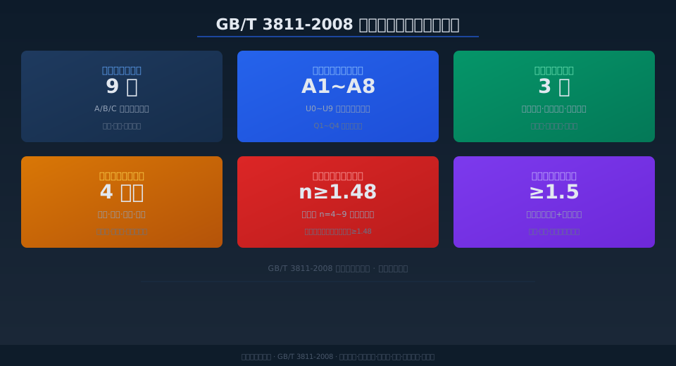
GB/T 3811 Core Design Parameters
Design Load Combinations
9
Categories A/B/C
Crane Classification
A1~A8
U0–U9 + Q1–Q4
Steel Structure Verification
3
Allowable / Limit / Deflection
Mechanism Types
4
Hoisting · Travel · Slewing · Luffing
Steel Safety Factor
≥1.48
Based on yield strength
Anti-Overturning Stability
≥1.5
Static + dynamic verification
Related Reading
- How to Select Crane Couplings? Gear, Elastic, Diaphragm & Drum-Type — Parameter Comparison and Shaft Alignment Procedure
- Crane Hoisting Motor Overheating or Burnout? 7-Cause Diagnostic Guide, Temperature Rise Limits & Protection Solutions
- GB/T 30024 — Verification of Load-Bearing Capacity of Crane Steel Structures: Standard Interpretation
- GB/T 6067.1 — Safety Code for Lifting Appliances: Standard Interpretation
Frequently Asked Questions
Q: What are the main design philosophy differences between GB/T 3811 and FEM 1.001?
A: GB/T 3811 adopts a dual-track system with the allowable stress method as the primary approach and the limit state method as a supplement, while FEM 1.001 is built around the partial safety factor limit state method. Three key differences stand out: ① For steel structures, GB/T 3811 applies a uniform yield safety factor of n ≥ 1.48, whereas FEM 1.001 uses partial factors γ_f and γ_m depending on the load combination; ② For classification, GB/T 3811 uses an eight-level system from A1 to A8, while FEM 1.001 uses a similar A1–A8 scale but defines the load spectrum Q slightly differently; ③ GB/T 3811 separately specifies an allowable deflection method to control deformation, whereas FEM 1.001 incorporates deformation control into the serviceability limit state. Kelude products exported to Europe are designed to meet both standards simultaneously.
Q: What minimum safety factors for wire ropes does GB/T 3811 require?
A: Clause 5.4.2 of GB/T 3811 specifies the minimum wire rope safety factor n based on the mechanism classification: M1–M3 require n = 4.0, M4 requires n = 4.5, M5 requires n = 5.6, M6 requires n = 7.1, M7 requires n = 8.0, and M8 requires n = 9.0. The safety factor is calculated as the ratio of the rope's minimum breaking force to the maximum static tension. For hazardous applications such as handling molten metal, the safety factor must be increased one level above the standard requirement. When using 4-strand or 6-strand regular lay wire rope, an additional rotation factor must also be considered.
Q: What should be done if a crane main girder deflects beyond the allowable limit after 5 years of service?
A: First, measure the actual mid-span deflection using a theodolite or total station and compare it against the allowable values specified in the GB/T 3811 annex (L/800 for bridge cranes, L/500 for gantry cranes). Remedial actions depend on the severity: ① If deflection is within L/600, the crane may remain in service but the inspection interval must be shortened to 6 months; ② If deflection exceeds L/600 but remains below L/400, flame straightening can be applied with heating temperature controlled between 600–700°C, followed by re-measurement after cooling; ③ If deflection exceeds L/400 or lateral bow is also out of tolerance, contact a professional manufacturer such as Kelude for main girder rework or replacement. After repair, a static load test at 1.25× rated capacity is mandatory. Preventing overload and avoiding skewed or angled lifting in daily operation are the fundamental measures to prevent main girder deflection.
Q: What is the approximate price of a 10-ton electric double-girder bridge crane designed to GB/T 3811 Crane Design Standard?
A: For a 10-ton QD Type electric double-girder bridge crane with a 22.5 m span, 9 m lifting height, and work duty A5, newly designed and manufactured to GB/T 3811 Crane Design Standard, the domestic market price typically ranges from approximately $11,100 to $17,800 (2026 reference price). Price variations mainly depend on: ① Hoisting mechanism configuration (Nanjing Special Motor vs. imported SEW-Eurodrive) — a difference of about $2,200–$4,400; ② Electrical control system (contactor-based control vs. variable-frequency speed control) — a difference of about $3,000–$4,400; ③ Steel structure coating grade (standard anti-corrosion C3 vs. heavy-duty anti-corrosion C5) — a difference of about $1,200–$2,200. Kelude Heavy Industry offers free selection assistance and load calculation reports, and can provide a precise quotation based on your actual operating conditions. Contact our consultation hotline for the latest pricing.
