

How to Choose Crane Couplings: Gear, Flexible Pin & Diaphragm Types
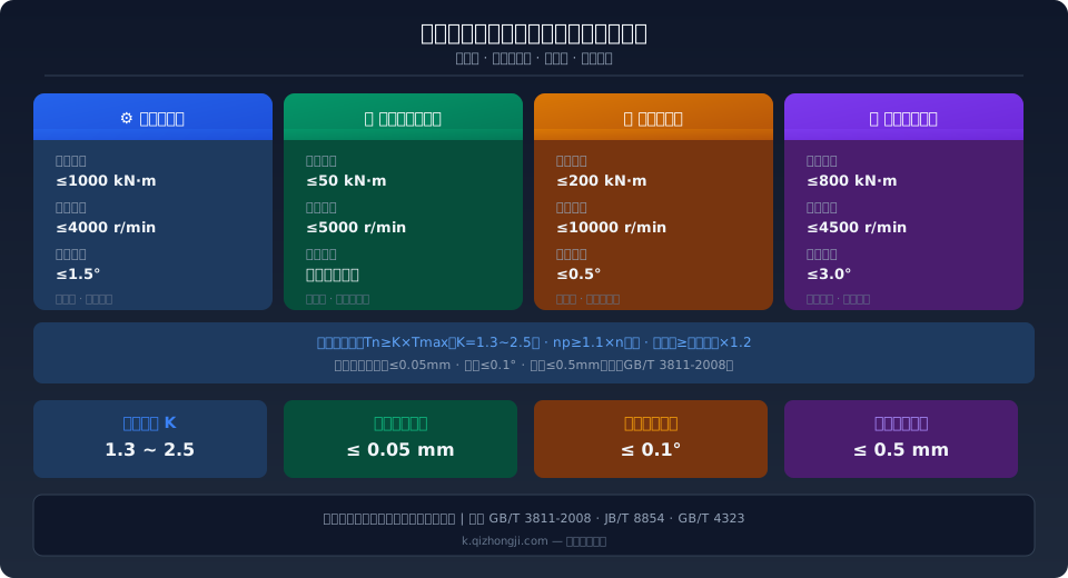
Crane couplings fall into four main categories: gear couplings (high load capacity, requires lubrication, ≤1000 kN·m), flexible pin couplings (vibration damping, maintenance-free, ≤50 kN·m), diaphragm couplings (lubrication-free, high-speed, ≤10,000 r/min), and crowned gear couplings (large misalignment compensation, ≤3.0°, best overall performance). The key selection parameters are nominal torque (Tn), permissible speed (np), and the three misalignment compensation values (radial, axial, and angular). Shaft alignment requirements call for radial deviation ≤0.05 mm and angular deviation ≤0.1°.
Couplings are critical transmission components in crane drive systems, connecting the electric motor to the gearbox and the gearbox to the drum or wheels. In the hoisting mechanism, they transmit motor torque to the gearbox high-speed shaft; in the travel mechanism, they handle torque transmission for the crane bridge and trolley movement. Improper coupling selection can lead to excessive vibration and premature failure of elastic elements in minor cases, or shaft breakage and production downtime in severe cases. This article examines the structural principles of the four mainstream coupling types and provides a systematic guide to torque verification, alignment tolerance standards, and installation and maintenance practices.
Coupling Types and Technical Characteristics
Couplings used in lifting appliances fall into two broad categories: rigid couplings and flexible couplings. Rigid couplings (such as flange couplings) require precise shaft alignment and are suitable for low-speed applications where accurate centering is achievable. Flexible couplings, which accommodate certain radial, axial, and angular misalignment, are the dominant choice in crane drive systems and are further divided into the following four main types:
Gear Coupling — Comprises an internal gear ring and an external gear shaft sleeve that transmit torque through gear tooth meshing. Nominal torque range: 0.4–1000 kN·m; permissible speed: ≤4000 r/min; angular misalignment capacity: ≤1.5°. Gear couplings offer the highest load-carrying capacity and are used in heavy-duty applications such as the main hoist of QD-type double-girder bridge cranes. Their drawbacks include the need for regular grease lubrication (typically every 500 operating hours) and increased backlash and impact loads as tooth surfaces wear. Per JB/T 8854, gear coupling tooth surface hardness should reach HRC45–52, with standard backlash of 0.2–0.5 mm.
Flexible Pin Coupling — Uses nylon pins or rubber elastic elements to transmit torque, absorbing vibration and shock through elastic deformation. Nominal torque range: 0.01–50 kN·m; permissible speed: ≤5000 r/min. Its primary advantage is maintenance-free operation — no lubrication required — and the elastic elements also provide overload protection (when torque exceeds the limit, the pins shear to protect the motor and gearbox). Suitable for medium- and low-torque applications such as the travel mechanism of LD-type single-girder cranes and the high-speed shaft of electric hoists. Elastic elements should be replaced immediately when cracking or permanent deformation exceeding 30% of original thickness is observed. Selection per GB/T 4323.
Diaphragm Coupling — Consists of multiple stainless steel diaphragm packs bolted between two hub halves, compensating for misalignment through elastic diaphragm deflection. Nominal torque range: 0.05–200 kN·m; permissible speed: up to 10,000 r/min or higher; angular compensation: ≤0.5°; axial compensation: ±3 mm. Diaphragm couplings are lubrication-free, backlash-free, and well suited for high-speed precision drives. They are widely used in variable-frequency speed control systems for hoisting mechanisms and in the long-travel mechanism of gantry cranes. The design fatigue life of the diaphragm is typically ≥10⁷ cycles; approaching end-of-life, crack propagation and stiffness degradation become evident.
Crowned Gear Coupling — An enhanced version of the gear coupling with a crowned (barrel-shaped) external tooth profile that increases contact area and misalignment capacity. Nominal torque range: up to 800 kN·m; angular misalignment capacity: up to ≤3.0° — the best overall performance of the four types. The crowned tooth surfaces undergo carburizing and quenchingrizing and quenching (effective case depth 0.8–1.2 mm), delivering approximately 30%–50% higher tooth contact strength than standard gear couplings. In metallurgical cranes (LDY type), ladle cranes, and other high-temperature applications involving frequent forward/reverse operation, crowned gear couplings are the preferred solution.
Key Selection Parameters for Crane Couplings
Coupling selection requires verification of three fundamental parameters:
① Nominal torque Tn must be equal to or greater than the calculated torque Tc (Tc = K × Tmax, where K is the service factor, 1.3–2.5)
② Permissible speed np must be at least 1.1 times the actual operating speed
③ Maximum radial, axial, and angular compensation must each exceed the measured installation deviation by a factor of 1.2. The following six critical indicators serve as the core decision-making criteria:
Coupling Parameter Comparison by Type
The table below compares four mainstream coupling types across four key dimensions — load capacity, misalignment compensation, maintenance requirements, and application scenarios — to provide a quantitative basis for your selection decision:
| Coupling Type | nominal torque (Tn)Range | Angular Misalignment Compensation | Maintenance Requirements | Typical Application Scenarios |
|---|---|---|---|---|
| Gear Coupling | 0.4~1000 k N·m | ≤1.5° | Per500hGrease Lubrication | QDdouble girder Main Hoisting / Lifting/Heavy Duty |
| flexible pin coupling | 0.01~50 k N·m | ≤1.0° | Maintenance-Free(Inspection Elasticity Component) | LDSingle Girder/Electric Hoist/Small and Medium Torque |
| diaphragm coupling | 0.05~200 k N·m | ≤0.5° | Free Lubrication/Maintenance-Free | Variable Frequency Speed Control/High Rotational speed/Precision Drive |
| crowned gear coupling | ≤800 k N·m | ≤3.0° | Per500hGrease Lubrication | Metallurgical/Casting/High-Temperature Reversing Duty |
| Flange Coupling(Rigid) | ≤50 k N·m | 0°(Strictshaft alignment) | Maintenance-Free | Low Speed/shaft alignment Accuracy High |
| Tire coupling | 0.1~25 k N·m | ≤2.5° | Carcass Inspection Aging | Heavy Shock/Vibrating Conditions |
Shaft Alignment Methods and Tolerance Standards
Coupling misalignment is the leading cause of excessive vibration, bearing damage, and premature failure of elastic components. Industry statistics indicate that approximately 65% of early coupling failures are directly attributed to poor shaft alignment. Alignment correction should be performed using the dial indicator method or laser alignment equipment, measuring both radial and angular deviation on the coupling's outer diameter and end face, then adjusting to meet the required tolerances.
Dial Indicator Method (Traditional Approach) — Mount two dial indicators on the reference half-coupling (motor shaft side), with the indicator tips contacting the outer diameter and end face of the adjustable half-coupling (gearbox shaft side). Slowly rotate the shaft through one full revolution (0° 90° 180° 270° 360°), recording readings at each position. Radial deviation Δr = |a1-a3|/2 (where a1 and a3 are readings at 0° and 180°), and angular deviation Δα = arctan(|b1-b3|/D) (where b is the face reading and D is the measurement diameter). Typical requirements: radial deviation ≤ 0.05 mm, angular deviation ≤ 0.1° (corresponding to an axial reading difference of ≤ 0.17 mm per 100 mm of measurement diameter).
Laser Alignment Method (Recommended) — The laser transmitter is mounted on the reference end and the receiver on the adjustable end. The instrument automatically calculates radial deviation, angular deviation, and required shim thickness. Measurement accuracy is ±0.001 mm, with an operation time of approximately 10–15 minutes (versus 30–45 minutes for the dial indicator method). Laser alignment is strongly recommended for large cranes (≥ 50 t QD Type) and multi-stage drive systems, as it minimizes rework caused by measurement errors. Follow the sequence "radial before angular, vertical before horizontal," and re-verify after each adjustment.
Permissible Alignment Tolerances — Referencing ISO 4301 Crane Design Standard and applicable installation specifications, permissible alignment tolerances by rotational speed are as follows: for speeds ≤ 1500 r/min, radial deviation ≤ 0.08 mm and angular deviation ≤ 0.12°; for speeds between 1500 and 3000 r/min, radial deviation ≤ 0.05 mm and angular deviation ≤ 0.10°; for speeds ≥ 3000 r/min, radial deviation ≤ 0.03 mm and angular deviation ≤ 0.08°. After installation, the coupling must undergo a no-load trial run of at least 30 minutes, with bearing housing vibration measured at ≤ 4.5 mm/s (per ISO 10816-3) to be considered acceptable.
Installation, Maintenance, and Troubleshooting Guide
Proper coupling installation is fundamental to reliable drive system operation. Key installation considerations: the half-coupling-to-shaft fit typically uses an H7/k6 or H7/m6 transition fit. Before assembly, clean the shaft journal and coupling bore, then apply a thin film of lubricating oil. For gear couplings and crowned gear couplings, inject 2# lithium grease through the grease fitting after installation until it overflows. For flexible pin couplings, the clearance between the nylon elastic pin and the pin hole should be 0.1–0.3 mm (too tight causes pin fracture; too loose results in impact loading). Diaphragm coupling bolts should be tightened in a diagonal sequence in 2–3 progressive passes to the specified torque (M10 bolts approximately 45 N·m, M12 approximately 75 N·m)ened in a diagonal sequence in 2–3 progressive passes to the specified torque (approximately 45 N·m for M10 bolts, 75 N·m for M12).
Routine inspection should focus on three key indicators during operation: abnormal noise, temperature rise, and vibration. Under normal operating conditions, the coupling housing temperature should not exceed ambient temperature by more than +40 °C (elastic type) or +60 °C (gear/crowned gear type). Shut down immediately for inspection if any of the following conditions occur:
① Periodic "clicking" sound — may indicate a fractured elastic pin or gear wear; inspect by opening the protective cover
② High-frequency metallic "hissing" or scraping sound — may indicate diaphragm fatigue cracking; replace the diaphragm pack
③ Bearing housing vibration suddenly increases to ≥ 7.1 mm/s — may indicate excessive misalignment; realign the coupling. The following table outlines common failure modes and corresponding troubleshooting approaches:
| Fault Symptom | Common Causes | Troubleshooting and Repair Procedures | Preventive Maintenance Interval |
|---|---|---|---|
| Coupling Abnormal noise/Vibration | Elasticity Component Wear/Gear Excessive Clearance | Inspect and Replace Elasticity Component; Measurement Backlash>0.5mm Replace When | Per Shift Inspection Acoustic Monitoring/Vibration Measurement |
| Elasticity Frequent Component Fracture | shaft alignment Deviation Exceeding Limit/overload | Re-shaft alignment(Radial≤0.05mm); Verify Actual Load | Re-verify After Each Replacementshaft alignment |
| Coupling Overheating>80℃ | Lubrication Insufficient/Grease Aging | Replenish or Replace2#Lithium-Based Grease; Inspection Seal | Per500hGrease Lubrication/Per2000hGrease Change |
| Diaphragm Crack | fatigue life Due/Angular Deviation Exceeding Limit | Replace Diaphragm Pack; Inspect and Correctshaft alignment Deviation≤0.1° | Per2000hVisual or Dye penetrant inspection |
| Pin Shear(Elasticity Type) | Instantaneousoverload/Pin Material Defect | Replace All Pins(Do Not Replace Only Broken Ones); Inspectionoverload Common Causes | Pin Inventory Spare parts≥1Set |
| Tooth Surface Pitting/Spalling | Lubrication Poor/Contact Stress Exceeded | Inspect and Replace Coupling; Improve Lubrication Conditions; Verify Torque | Per4000hTooth Surface Inspection |
Related Reading: Coupling selection and shaft alignment must follow the overall design specifications. Refer to the transmission system safety factor requirements in ISO 4301 Crane Design Standard. Since brakes and couplings are both critical transmission components, their selection must be coordinated — see the Crane Brake Selection Guide for braking torque verification methods. Additionally, TSG 51-2023 Crane Safety Technical Supervision Regulation specifies clear periodic inspection requirements for key transmission components.
Frequently Asked Questions
Q: What's the difference between a gear coupling and a crowned gear coupling? When should I choose the crowned type?
A: A standard gear coupling has straight-cut external teeth, while a crowned gear coupling features externally machined teeth with an arc-shaped crown (crowning amount 0.02–0.06 mm). This increases the contact area and reduces tooth contact stress by 30%–50%. The crowned design offers angular misalignment compensation up to 3.0° (compared to only 1.5° for standard gear types), making it better suited for metallurgical and foundry cranes operating in high-temperature environments with frequent forward/reverse rotation. When the work duty is ≥A6 with frequent start-stop braking, the crowned gear coupling is the preferred choice (per the ISO 4301 transmission selection recommendation table). For general applications rated A3 to A5, a standard gear coupling offers better cost-effectiveness.
Q: How does ISO 4301 define the coupling safety factor K? What values apply to different mechanisms?
A: Per ISO 4301 Section 5.3.2, the coupling selection torque is calculated as Tc = K × Tmax, where K is the service factor. For hoisting mechanisms, K = 2.0–2.5 (accounting for the dynamic load factor φ₂ = 1.1–1.3). For travel mechanisms, K = 1.3–1.8 (A3–A5: 1.3–1.5; A6–A8: 1.6–1.8). For slewing mechanisms, K = 1.5–2.0. Important note: for metallurgical cranes (M7–M8), the K value must be multiplied by an additional 1.2× factor because high-temperature environments (≥60°C) degrade the performance of elastic components and grease. The permissible speed (np) must also satisfy np ≥ 1.1 × n_operating.
Q: Why do the elastic pins in my coupling keep breaking — three times now? How do I fix this permanently?
A: Repeated elastic pin fractures typically stem from three root causes: ① Excessive shaft misalignment (radial > 0.05 mm or angular > 0.1°), which subjects the pins to additional alternating bending stress — this is the most common cause, accounting for over 60% of cases; ② Actual load exceeding the coupling's rated torque range, possibly from momentary overload during full-load hoisting combined with wind loading; ③ Substandard pin material or hardness (nylon pins should be PA6 or PA66 with Rockwell hardness ≥ R115). Recommended troubleshooting sequence: first, re-verify alignment data using a laser alignment tool; second, measure motor current under full-load conditions with a clamp meter to back-calculate actual torque; finally, check whether the pins have material certification reports. A permanent fix requires correcting the misalignment and re-verifying the coupling torque rating simultaneously.
Q: How much does a flexible pin coupling cost? Do I have to remove the motor to replace it?
A: The complete flexible pin coupling assembly varies significantly by model and capacity: LT type (torque ≤ 250 N·m) costs approximately $30–$90 per set, suitable for electric hoists under 5 t; LX type (torque ≤ 50 kN·m) costs approximately $120–$370 per set, suitable for LD type single-girder cranes rated 10–20 t. Replacing just the elastic pin set (excluding the coupling halves) costs approximately $15–$75. Whether the motor must be removed depends on available installation space: if there's ≥ 150 mm axial clearance between the motor and gearbox, pins can be replaced without removing the motor; otherwise, the motor anchor bolts must be loosened and the motor shifted axially. We recommend specifying an extended-length flexible pin coupling (center section extended ≥ 200 mm) at the time of ordering to enable future pin replacement without motor removal.
Kelude Heavy Industry offers a full range of crane coupling selection and on-site shaft alignment services, supporting non-standard customization across four coupling types: gear, flexible pin, diaphragm, and crowned gear. Our technical team is equipped with laser alignment instruments and vibration analysis systems, providing end-to-end solutions from selection calculations to installation & commissioning.
