

Bridge Crane Trolley Frame Deformation: Detection & Straightening
The crane trolley frame is the load-bearing platform for the hoisting mechanism and trolley travel mechanism of a bridge crane. Its flatness (diagonal difference ≤5mm, four-point elevation difference ≤3mm) and structural integrity directly affect the overall operating accuracy and service life of the crane. This article covers 5 measurement methods (level instrument / laser tracker / wire stretching / total station / 3D scanning), flame straightening procedures (heating temperature 600~750°C, triangular heating zone width 20~40mm), and mechanical straightening parameters, providing complete engineering guidance in accordance with FEM 1.001 and ISO 4301 standards.
The trolley frame of a bridge crane is the structural platform that supports the hoisting mechanism (electric motor, reducer, brake, drum) and the trolley travel mechanism. It is typically fabricated as a welded frame structure using H-beams or box girders. Under prolonged heavy loads, frequent start-stop cycles, and eccentric loading conditions, the trolley frame can develop warping, diagonal distortion, and sagging at mounting surfaces. These deformations lead to wheel flange wear, increased gearbox shaft misalignment, and unsynchronized brake operation. Timely detection of deformation and safe correction are critical to maintaining crane operational safety.
This article follows the requirements of FEM 1.001 — General Purpose Bridge Cranes and ISO 4301 — Crane Design Standard, and provides a systematic overview of 5 deformation detection methods, allowable deformation criteria, flame straightening and mechanical straightening procedures, and post-correction verification processes.
Trolley Frame Deformation Measurement Methods
Deformation measurement should be performed with the crane unloaded and the trolley positioned at mid-span of the main girder. The frame surface must be free of oil and debris. Before taking measurements, clean the reference surfaces with a wire brush or angle grinder to achieve a surface finish of Ra≤6.3μm. The following five methods are presented in order of increasing accuracy for both field and workshop applications.
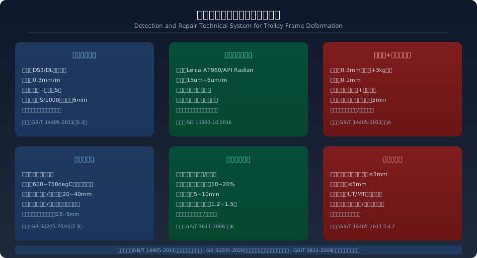
Level Instrument Method — Using a DS3 or DL-class automatic level with an invar staff, set up 5 measurement points at the four corners and center of the trolley frame. Take three readings at each point and average them to determine relative elevation deviations. This method provides flatness accuracy within ±0.3mm/m and is well suited for routine inspections and quick screening of small-to-medium bridge cranes (lifting capacity ≤50t). Per FEM 1.001 Section 5.3, the diagonal difference of the trolley frame flatness must not exceed 5mm, and the four-corner elevation difference must not exceed 3mm.
Laser Tracker Method — Using a Leica AT960 or API Radian laser tracker with a spherically mounted retroreflector (SMR), collect 3D coordinate point clouds on the top surface and critical mounting faces of the trolley frame. Single-point measurement accuracy reaches 15μm+6μm/m, and the entire top surface (approximately 2m×3m) can be scanned within 10 minutes with real-time 3D deviation heatmap generation. This method is ideal for factory pre-assembly inspection or post-overhaul precision measurement of large bridge cranes (lifting capacity ≥50t), and can simultaneously evaluate flatness, parallelism, and perpendicularity tolerances.
Wire Stretching Method — Stretch a 0.3mm diameter piano wire under a 3kg tension weight across the diagonal corners of the trolley frame, then measure the distance from the wire to the frame surface at multiple points using an inside micrometer. This method offers an accuracy of approximately ±0.1mm with minimal equipment cost (the complete kit costs under $75), making it the most economical on-site solution for diagonal distortion detection. However, measurement throughput is relatively low (about 30 minutes per data set), and results are sensitive to ambient wind and temperature variations.
Total Station Method — Using a Leica TS16 or TS60 total station with a free-station setup, establish 3 to 4 control points around the trolley frame and obtain 3D coordinates of each measurement point through polar measurement principles. Accuracy is approximately ±1mm+2ppm, making this method suitable for non-contact measurement of large-span (greater than 6m) trolley frames. Dedicated measurement software enables automatic adjustment calculations and graphical report generation.
3D Laser Scanning Method — Using a handheld 3D scanner (e.g., Creaform HandySCAN 307, accuracy ±0.05mm, resolution 0.1mm), perform a full-surface scan of the trolley frame to generate a high-density point cloud (point spacing 0.2mm). Using Geomagic or PolyWorks software, compare the scan data against the CAD nominal model to visually identify the location, extent, and magnitude of deformation. This method is widely adopted by heavy fabrication shops and third-party inspection bodies, though the equipment investment is substantial (approximately $44,000–$74,000 per system).
Measurement Method Comparison: Accuracy vs. Cost
Each of the five measurement methods offers distinct trade-offs in accuracy, efficiency, cost, and application scenarios. When selecting a method, consider the trolley frame size (span 2–8m), required accuracy level (routine check / precision inspection / arbitration testing), and site conditions (indoor vs. outdoor, temperature variation, vibration interference). The following cards summarize the accuracy grades and recommended equipment for each method:
| Measurement Method | Accuracy Grade | Applicable Working Conditions | Reference Standard |
|---|---|---|---|
| Level Instrument(DS3/DLGrade) | ±0.3mm/m | On-site Quick Inspection, Routine Maintenance | FEM 1.001 5.3 |
| laser tracker(AT960) | ±15μm+6μm/m | Factory Pre-installation, Accuracy High-requirement Detection | ISO 10360-10:2016 |
| Wire Stretching Method+Inside Micrometer | ±0.1mm | Cost-effective On-site Solution, Diagonal Measurement | FEM 1.001 Appendix A |
| total station(TS16/TS60) | ±1mm+2ppm | Large Span Trolley Frame, Long-distance Measurement | GB 50026-2020 |
| 3D Laser Scanning(Handy SCAN) | ±0.05mm | 3DDeformation Visualization, Reverse Modeling | GB/T 31004-2014 |
| Coordinate Measuring Machine (CMM)(CMM) | ±3μm | Laboratory High-precision Accuracy Metrology, Arbitration Detection | GB/T 16857Series |
Trolley Frame Deformation Limits & Acceptance Criteria
Evaluating trolley frame deformation requires simultaneous compliance with multiple standards. FEM 1.001 sets the manufacturing and acceptance standard for complete bridge cranes, including geometric tolerance requirements for the trolley frame in Section 5.3. GB 50205-2020, the Acceptance Standard for Steel Structure Construction Quality, provides more detailed allowable deformation values for welded steel structural components. In practice, Kelude Heavy Industry recommends adopting internal control limits 30%–50% stricter than the national standard to reserve deformation allowance for long-term service.
Flatness Evaluation — Based on elevation readings at the four corners and center of the trolley frame top surface, the flatness deviation is calculated as the difference between the highest and lowest points. A deviation ≤3 mm is acceptable; 3–5 mm is tolerable but requires periodic monitoring; anything greater than 5 mm must be corrected. If the diagonal measurement difference exceeds 5 mm, the trolley frame has undergone torsional deformation, and priority should be given to inspecting the four corner fillet welds for cracking.
Mounting Surface Flatness Evaluation — The reducer mounting surface must maintain flatness ≤0.5 mm over a 500 mm × 500 mm area per FEM 1.001, or ≤0.3 mm under the stricter GB 50205 requirement. The coaxiality of the drum support bearing housing mounting bases must be ≤0.2 mm, with the centerline height difference between the two bearing housings not exceeding 0.15 mm. The brake mounting base flatness must be ≤0.1 mm per 100 mm.
| Inspection Item | FEM 1.001Allowable Value | GB 50205Allowable Value | Kruud Recommended Internal Control Value |
|---|---|---|---|
| Trolley Frame Flatness | Diagonal Difference≤5mm | L/1000And≤5mm | ≤3mm(Strict50%) |
| Four Corners Elevation Difference | ≤3mm | ≤3mm | ≤2mm(Improve50%) |
| Wheel Support Surface Flatness | ≤1mm | ≤1mm | ≤0.7mm |
| Reducer / Gearbox Mounting Surface Flatness | ≤0.5mm/500mm | ≤0.3mm/500mm | ≤0.2mm/500mm |
| Drum Support Base Coaxiality | ≤0.2mm | ≤0.15mm | ≤0.1mm |
| Trolley Frame Diagonal Length Difference | ≤5mm | ≤3mm | ≤2mm |
Flame Straightening Procedure and Temperature Control
Flame straightening exploits the thermal expansion and contraction of steel. Localized heating creates compressive plastic deformation in the heated zone, and the shrinkage stress generated during cooling corrects the distortion. This method is suitable for welded structures made of Q235B or Q345B steel where the trolley frame flatness deviation is between 0.5 and 5 mm. While flame straightening is cost-effective—requiring no heavy equipment—it demands a high level of operator skill. Strict adherence to three key parameters is essential: heating temperature, heating pattern, and cooling method.
Heating Temperature Control—Use a neutral oxy-acetylene flame, maintaining the heating temperature strictly between 600 and 750°C (the steel surface will appear dark cherry red). Below 550°C, plastic deformation is insufficient and the correction effect is negligible. Exceeding 850°C causes grain coarsening, which can reduce mechanical properties (yield strength drops by 10%–15%). Monitor the temperature continuously using an infrared thermometer (accuracy ±2°C) or temperature-indicating crayons (TemPil 650°C/700°C/750°C grades). For Q345B steel, keep the maximum heating temperature approximately 50°C lower than for Q235B (i.e., 550–700°C) to prevent excessive grain growth in the heat-affected zone.
Heating Pattern Selection—Choose the heating pattern based on the type of deformation: ① For wave-shaped flatness distortion, use triangular heating zones (apex pointing toward the crown of the bulge, base width 20–40 mm, height 80–120 mm) spaced 200–300 mm apart; ② For longitudinal bowing, use strip heating zones (20–30 mm wide, running the full length of the deformed section), arranging 3–5 heating strips evenly along the member; ③ For angular distortion caused by weld shrinkage, apply linear heating (8–12 mm wide) on the weld root side, positioned 15–20 mm from the weld centerline. Always start heating at the point of maximum deformation and work outward toward both ends.
Cooling Method Selection—After flame heating, allow the part to cool naturally in still air (cooling rate approximately 5–10°C/min) to ensure the straightening stresses are released uniformly. For severe warping exceeding 3 mm, once the heated zone has cooled to 300–400°C, accelerate local cooling with a damp cloth (wrung out so it does not drip) to generate greater shrinkage stress. However, never quench the surface with direct water spray (cooling rates above 100°C/min), as this can cause surface hardening (hardness increases by HB50–80) and may even induce micro-cracks.
Mechanical Straightening with Hydraulic Jacks and Presses
Mechanical straightening applies a reverse bending moment to the deformed member using hydraulic jacks, screw presses, or dedicated straightening equipment, inducing plastic deformation to correct the distortion. This method is ideal for correcting side bow and camber in beam-type components (such as the main girders and cross beams of a trolley frame), as well as for severe warping exceeding 5 mm where the welds remain intact. Unlike flame straightening, mechanical straightening does not alter the material's metallurgical structure, but it does require substantial equipment capacity.
Incremental Loading and Pressure Holding—Use a hydraulic jack (rated pressure ≥20 MPa, stroke ≥100 mm) with rigid supports (temporary support frames welded from H-beam sections) to apply the counterforce to the deformed area. Apply the load in 5–6 increments, each step adding 15%–20% of the target corrective force. Hold the pressure for 5–10 minutes after each increment to allow stress to distribute fully. The total applied force must not exceed 80% of the material's yield strength (approximately 188 MPa for Q235B and 276 MPa for Q345B) to prevent local crushing. Set the over-bend amount (reverse pre-deformation) at 1.2–1.5 times the target correction to compensate for elastic springback.
Support and Loading Point Arrangement—The three-point bending setup (two supports, one loading point) is the most common arrangement. Space the supports at 70%–80% of the deformed section length, and place 15–20 mm thick steel plates under the supports to distribute contact stress. Position the loading point at the midpoint between the two supports, and place an 8–10 mm thick copper or aluminum pad under the loading point to protect the component surface from indentation. For severe bends exceeding 8 mm, use a four-point bending arrangement (two supports, two loading points) to create a pure bending zone in the middle of the deformed section, resulting in a more uniform correction.
Post-Straightening Stress Relief—Mechanical straightening leaves significant residual stress in the component (up to 30%–50% of the material's yield strength), so stress relief treatment is mandatory. Vibratory stress relief (VSR) is recommended for 30–45 minutes, with the excitation frequency set within 1/3 to 2/3 of the component's first natural frequency and dynamic stress controlled at 10%–20% of the yield strength. If VSR equipment is unavailable, natural aging (7–14 days) or low-temperature tempering (heat to 200–250°C, hold for 2 hours, then cool in the furnace to below 150°C before removal) are acceptable alternatives.
Post-Straightening Verification and Return-to-Service Criteria
After straightening is complete, a systematic re-inspection must be carried out to confirm that geometric dimensions, weld integrity, and operational performance all meet the required standards before the equipment is returned to service. The verification process consists of three steps: geometric re-measurement, non-destructive testing of welds, and no-load/rated-load test runs.
Step 1: Geometric Re-Measurement—Re-measure the trolley frame using the same level of precision as the initial inspection. Flatness deviation must return to within the allowable tolerance (diagonal difference ≤5 mm, elevation difference at the four corners ≤3 mm). If the deviation remains out of tolerance after straightening, analyze the cause of residual deformation (possible causes include insufficient heating, inadequate pressure application, or excessive elastic springback), adjust the straightening parameters, and perform a second correction. Do not repeat flame straightening on the same area more than three times; if a third pass is insufficient, the component should be replaced.
Step 2: Non-Destructive Testing of Welds—All welds and heat-affected zones within the straightened area and a 300 mm perimeter must undergo non-destructive testing. Use Ultrasonic Testing (UT) in accordance with GB/T 11345-2013 (Level B) to detect internal defects, and Magnetic Particle Inspection (MPI) per GB/T 26951-2011 to detect surface and near-surface cracks. Pay particular attention to the edges of heated zones, the apexes of triangular heating patterns, and the areas beneath mechanical press support points. Any cracks found must be ground out, re-welded, and re-tested using both UT and MPI.
Step 3: No-Load and Rated-Load Test Runs—After the trolley frame has been straightened, reinstall the hoisting and trolley travel mechanisms. Begin with a no-load continuous test run of at least 30 minutes (trolley traverses the full length at least 10 times; hoist completes at least 5 full up/down cycles). Check for smooth operation, abnormal noise, and abnormal vibration. Once the no-load test passes, proceed to a rated-load test (lift the rated load and complete at least 3 cycles of hoisting, lowering, and trolley travel), confirming that the reducer and brake operate normally and that the mounting surfaces show no secondary deformation. After all tests pass, record the straightening date, measurement data, and test results in the equipment maintenance file.
Related Reading
More overhead crane maintenance and repair technical articles:
Frequently Asked Questions
Q: Can flame straightening fix a trolley frame with a flatness deviation exceeding 5 mm? How many correction passes are needed?
A: Yes. Flame straightening is effective for flatness deviations in the 5–8 mm range. Typically, 1–2 heating passes will bring the deviation to within 3 mm. Procedure: First, use the wire-stretching method to locate the point of maximum deformation (usually near the reducer mounting base). Apply a triangular heating zone (base width 40 mm, height 120 mm) at a temperature of 650–700°C (dark cherry red), allow natural air cooling, and re-measure. If a residual deviation of 2–3 mm remains after the first pass, a second pass can be performed after an interval of at least 4 hours, but do not exceed 3 cumulative heating passes on the same area. For severe deformation exceeding 8 mm or where weld cracking is present, component replacement is recommended over straightening.
Q: Is ultrasonic testing mandatory after flame straightening? Which areas need to be inspected and what are the acceptance criteria? What specific locations should be checked?
A: After flame straightening, non-destructive testing of the heated zones is mandatory. Ultrasonic Testing (UT) per ISO 17640 (replacing GB/T 11345-2013) at Level B inspection grade shall be performed, focusing on three critical locations: ① The apex of the triangular heating zone — where the temperature gradient is steepest and thermal stress concentrates, making it prone to micro-cracking; ② The boundary between heated and unheated metal — a microstructurally distinct interface that serves as a high-risk initiation site for cracks; ③ Existing fillet and butt welds — flame heating can cause pre-existing minor defects within the weld to propagate. Additionally, Magnetic Particle Inspection (MPI) per ISO 9934-1 (replacing GB/T 26951-2011) shall be used to detect surface-breaking defects.
Q: What causes trolley frame deformation on overhead cranes, and how can it be prevented?
A: Trolley frame deformation typically stems from four root causes: ① Prolonged off-center loading — when the load's center of gravity deviates more than 200 mm from the trolley centerline, the frame is subjected to additional torque, which is the leading cause of diagonal distortion (accounting for roughly 45% of reported cases); ② Hoisting impact loads — if acceleration during a full-load lift exceeds 0.5 m/s², the resulting shock is transmitted through the wire rope to the trolley frame, and the cumulative fatigue effect causes the mounting surfaces to settle; ③ Relief of welding residual stress — within the first 1–2 years of service, gradual stress relief from manufacturing welds can produce natural deformation of 0.5–3 mm; ④ Misaligned trolley rail joints — when the vertical step at a rail joint exceeds 1 mm, the trolley experiences impact vibration on every pass, accelerating fatigue deformation of the frame. Preventive Action: strictly adhere to the rated load (never exceed it by more than 10%), inspect trolley frame flatness quarterly, and perform a full dimensional re-survey annually.
Q: How much does trolley frame flatness inspection cost? What is the most economical and reliable method for routine checks? Can a spirit level replace professional inspection?
A: Costs vary significantly by method: the level instrument method (using in-house equipment) carries a labor cost of roughly $45–$75 per inspection; the wire-pull method requires less than $15 in consumables and is well suited for in-house checks; outsourced laser tracker measurement runs approximately $300–$520 per inspection (report included); and outsourced 3D scanning costs about $450–$740 per inspection. For routine inspections, we recommend investing in a DS3-grade level instrument (about $370–$590) paired with an invar staff (around $120); a two-person crew can complete a single trolley frame check in 30 minutes, with accuracy fully adequate for routine maintenance needs. We suggest performing in-house checks three times per year (quarterly) and commissioning a professional precision survey (laser tracker or 3D scanning) every two years as a baseline calibration. However, a level instrument cannot detect local flatness deviations on wheel mounting surfaces (which must be ≤1 mm); these precision interfaces still require dedicated professional equipment.
Kelude Heavy Industry provides complete engineering services for overhead crane trolley frame deformation inspection, straightening, and repair, covering the full range of bridge cranes from 5t to 500t. Equipped with a Leica AT960 laser tracker, HandySCAN 307 3D scanner, and Olympus EPOCH 650 ultrasonic flaw detector, we deliver turnkey solutions from on-site diagnosis and corrective work to final verification.
