

Crane Brake Selection Guide: Torque, Safety Factor & Config
The electromagnetic brake is the last line of defense in crane safety braking — the core selection criterion is ensuring the braking torque is greater than or equal to 1.5 times the rated load torque, with a hoisting mechanism safety factor of K≥1.5 (K≥1.75 for metallurgical applications), and verifying each parameter against GB/T 22414-2008 "Technical Conditions for Hoisting Mechanism Braking Systems of Cranes" and the relevant requirements of TSG 51-2023 Crane Safety Technical Supervision Regulation.
Crane brakes are the most critical safety devices in both hoisting and travel mechanisms, directly impacting personnel safety and equipment protection. At Kelude Heavy Industry, brake selection is treated as the primary safety verification step in every crane package design, and all factory-delivered equipment is configured with braking systems that meet or exceed the safety factors specified in ISO 4301 Crane Design Standard. Per GB/T 24811 "Brakes for Cranes" and ISO 4301, the hoisting mechanism must be equipped with two independent brakes — a service brake and an emergency brake — and if either one fails, the other must be capable of independently braking the rated load. Travel mechanisms, in turn, must bring the crane to a complete stop within a specified braking distance after power is cut off.
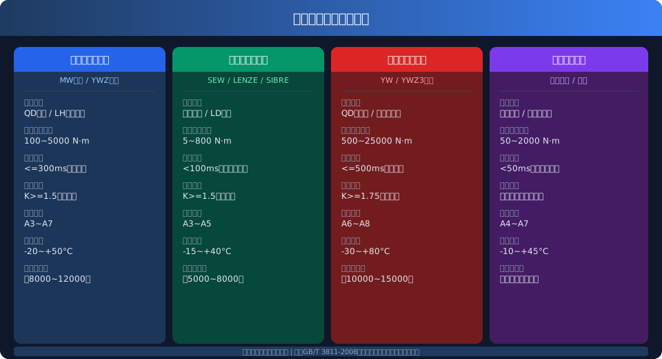
Brakes commonly used in today's crane industry fall into four main categories: electromagnetic drum brakes (MW/YWZ series), electromagnetic disc brakes (SEW/LENZE type), hydraulic thrustor brakes (YWZ3 series), and eddy-current auxiliary brakes. Each type differs in response speed, braking torque range, applicable work duty classification, and installation/maintenance requirements, so selection must be based on a comprehensive evaluation of the crane's duty classification, rated lifting capacity, travel speed, and other parameters.
How Electromagnetic Brakes Work: Types and Applications
Electromagnetic drum brakes are the most widely used type on overhead cranes. They operate on the principle of an electromagnet that engages when energized and releases when de-energized, with spring force pressing the brake shoes against the brake wheel to achieve braking. The braking torque range is 100–5,000 N·m, with a response time of ≤300 ms (DC supply), making them suitable for hoisting mechanisms and crane travel mechanisms on QD double-girder and LH hoist-type double-girder cranes rated at A3 to A7 duty classifications. Their advantages include a compact structure and stable torque output; the drawbacks are that friction linings require periodic replacement and torque output may degrade in high-temperature environments.
Electromagnetic disc brakes use a multi-disc axial compression structure, offering a smaller footprint and faster response (<100 ms) than drum brakes, with a braking torque range of 5–800 N·m. They are primarily paired with electric hoists and LD single-girder crane hoisting motors (conical rotor brake motors), and are also widely used in SEW, LENZE, and other European-style geared motors. Because the friction area is relatively small, their duty classification is limited to A3 to A5, making them unsuitable for frequent start-stop duty cycles.
Hydraulic thrustor brakes use a hydraulic cylinder to drive the thrustor, which opens and closes the brake shoes. Braking torque can easily reach 500–25,000 N·m, making them ideal for heavy-duty applications such as large-tonnage QD double-girder bridge cranes, metallurgical cranes, and ladle cranes rated at A6 to A8 duty classifications. The hydraulic system delivers smooth torque output and gentle brake release, reducing mechanical shock. The downsides are the need for periodic hydraulic oil replacement and inspection of line seals, plus the requirement for low-temperature hydraulic oil in cold environments.
Eddy-current brakes generate braking torque through electromagnetic induction, with no mechanical contact or friction wear and extremely fast response (<50 ms). They are mainly used for precision positioning and auxiliary speed-control braking on high-speed cranes. Since eddy-current torque decays to zero as speed decreases, they cannot serve as the sole safety braking device and must be used in conjunction with mechanical brakes.
Braking Torque Calculation: The Core Formula
Calculating the braking torque for the hoisting mechanism is the most critical step in brake selection. According to Clause 5.3.2 of ISO 4301, the braking torque of the hoisting mechanism's service brake must satisfy the following fundamental condition: the braking torque Mb generated by the brake must not be less than the static torque Ms produced by the rated lifting load on the brake shaft, multiplied by the safety factor K. The basic calculation formula is as follows:
Mb = K × Ms = K × (Q × g × D) / (2 × n × i × η)
Where: Mb — minimum required braking torque (N·m)
Q — rated lifting capacity (kg), including the lifting spreader dead weight
D — drum diameter (m)
n — wire rope pulley ratio
i — reducer gear ratio
η — overall transmission efficiency (typically 0.85–0.92)
K — braking safety factor (K≥1.5 for hoisting mechanisms; K≥1.75 for metallurgical applications)
For crane bridge travel and trolley travel mechanisms, the braking torque must be sufficient to bring the mechanism to a stop within the specified braking distance. Per Appendix B of ISO 4301, the design braking distance for travel mechanisms is generally taken as the distance corresponding to 1/15 to 1/20 of the travel speed. The safety factor K for travel mechanism brakes is typically 1.25–1.5.
Safety Factors and Brake Selection Verification Method
The braking safety factor K is the most critical parameter in brake selection verification. On the same crane, different mechanisms require different safety factors. The hoisting mechanism demands the strictest requirements because it directly involves personnel safety — K≥1.5 for normal duty, K≥1.75 for metallurgical and foundry applications involving molten metal handling, and K≥2.0 for special applications such as nuclear power plants. Travel mechanisms require relatively lower safety factors: K≥1.25 for crane bridge travel brakes and K≥1.25–1.5 for trolley travel brakes.
The Kelude Heavy Industry engineering team recommends a four-step selection verification process: First, calculate the minimum static torque Ms on the brake shaft based on the crane's rated load and mechanism parameters. Second, determine the required safety factor K for the specific duty condition and calculate the design braking torque Mb = K × Ms. Third, select a brake model from the product catalog whose rated torque is ≥ Mb. Fourth, verify that the brake's thermal capacity and friction lining service life meet the duty classification requirements (checking braking frequency per hour and braking work).
Installation space and motor interface compatibility must also be verified. For European electric hoists (such as CD1 and MD1 types), the brake is typically integrated inside the conical rotor motor, so selection is done by simply matching the motor model. For QD-type double-girder cranes with independent brake configurations, you must verify that the brake wheel diameter, shaft bore dimensions, and anchor bolt hole spacing are compatible.
Brake Selection Quick Reference by Crane Type
The following table lists recommended brake types and key parameters for common crane tonnages and configurations for quick reference during selection:
Kelude Heavy Industry: Overhead Crane & Gantry Crane Solutions
Kelude Heavy Industry is a leading manufacturer of overhead cranes, gantry cranes, and electric hoists, delivering reliable material handling solutions for industrial applications across the United States and Europe. Our product line is engineered for durability, precision, and safety, meeting the demands of workshops, warehouses, and heavy fabrication facilities.
Frequently Asked Questions
Q: What is the typical lead time for a custom overhead crane?
A: Lead time varies based on configuration and capacity, but standard models typically ship within 4-6 weeks. Custom engineered solutions may require 8-12 weeks.
Q: Do you provide installation services?
A: Yes, we offer professional installation supervision and detailed manuals. For complex projects, we can dispatch our technical team to oversee the installation process.
Q: Can your cranes be used in explosion-proof areas?
A: Absolutely. We offer explosion-proof hoists and crane systems that comply with international standards, ensuring safe operation in hazardous locations.
Q: What is the warranty period for your products?
A: We provide a standard 12-month warranty on all crane components, with extended warranty options available upon request.
Q: Do you offer spare parts for older models?
A: Yes, we maintain an extensive inventory of spare parts for most crane models. Please contact us with your specific model and serial number for availability.
Q: Can you customize the crane controls for our existing facility?
A: Certainly. We offer various control options, including pendant, remote, and automated systems, which can be integrated with your current infrastructure.
| crane Type | Capacity Range | Recommended Brake Type | Braking torque Requirement | Safety factor K | Remarks |
|---|---|---|---|---|---|
| LD Type Single Girder Crane | 1~10t | electromagnetic disc brake type (conical motor built-in) | 10~150 N·m | ≥1.5 | Hoist Integral, No Separate Selection Required |
| LD Type Single Girder Crane | 12.5~20t | electromagnetic disc brake type + electromagnetic drum brake type | 150~600 N·m | ≥1.5 | Auxiliary Recommended for Large Capacities Braking |
| LH Type Hoistdouble girder | 5~20t | Electromagnetic Drum Type MWSeries | 200~800 N·m | ≥1.5 | With Independent Brake wheel |
| QD Typedouble girder(Light Duty) | 5~32t | Electromagnetic Drum Type YWZSeries | 300~2000 N·m | ≥1.5 | A3~A5Duty Recommended MW Type |
| QD Typedouble girder(Medium Duty) | 5~50t | hydraulic thruster YWZ3Series | 500~5000 N·m | ≥1.5 | A5~A6Duty Recommended Hydraulic Type |
| QD Typedouble girder(Heavy Duty) | 50~500t | hydraulic thruster + Disc Typeredundancy | 3000~25000 N·m | ≥1.75 | A7~A8Metallurgical Duty |
| LDYMetallurgical Single Girder | 1~20t | electromagnetic lifting magnet Type(HInsulation Class) | 30~500 N·m | ≥1.75 | High Temperature Resistant Friction lining+Dual Brake |
Brake Installation & Commissioning: Key Adjustment and Maintenance Tips
A: Proper brake installation is critical to braking performance and overall equipment safety. During installation, the coaxiality deviation between the brake wheel and the brake must not exceed 0.1 mm, and the contact area between the brake shoe and the brake wheel must be at least 80%. The initial clearance between the friction lining and the brake wheel should be set strictly in accordance with the product manual—typically 0.5–0.8 mm for electromagnetic drum brakes, 0.8–1.2 mm for hydraulic thrust brakes, and 0.3–0.5 mm for disc brakes.
During commissioning, both no-load and rated-load braking tests must be performed (every crane shipped from Kelude is individually tested to this standard) to verify that braking distance and load drop meet the requirements of TSG 51-2023 Crane Safety Technical Supervision Regulation. For hoisting mechanisms holding a rated load, the load drop must not exceed 1/100 of the rated lifting speed (with an absolute maximum of 200 mm). For travel mechanisms, the braking distance at rated speed must remain within ±15% of the design value.
| Maintenance Item | Inspection Interval | Technical Requirement | Acceptance Criteria Standard | Remarks |
|---|---|---|---|---|
| Friction lining Thickness | Visual Check per Shift / Weekly Measurement | Thickness≥of Original Thickness50% | <50%Replace Immediately | ultrasonic thickness gauge |
| Brake Clearance | Weekly Air Compressor | Drum Type0.5~0.8mm / Disc Type0.3~0.5mm | Exceeds Limit±20%i.e.Air Compressor | Feeler Gauge Measurement |
| Hydraulic Oil Quality | Quarterly | Moisture Content<0.1% / Cleanliness NAS (Australian Standard)≤10Light Duty | Change Oil if Exceeds Limit | YWZ3Series Caution |
| Spring Preload | Semi-annually | Measured Torque≥Rated Torqueof Original Thickness90% | <90%Replace Immediately Spring | Torque Wrench Detection |
| electrical wiring | Quarterly | Insulation Resistance≥1MΩ | If Less, Dry Treatment | 500VMegohmmeter (Insulation Tester) |
| Brake wheel Surface | Semi-annually | Surface Roughness Ra≤3.2μm | Groove>0.5mm Turning Repair | Roughness Gauge |
Engineering Calculation Examples
Example 1: Hoist Brake Verification for a 5t LD-Type Single-Girder Crane
Given: Rated lifting capacity Q=5000 kg, spreader dead weight ≈150 kg, drum diameter D=0.3 m, pulley ratio n=2, gearbox ratio i=58, transmission efficiency η=0.88, duty classification A4. Static torque: Ms=(5150×9.8×0.3)/(2×2×58×0.88)=74.2 N·m. With a safety factor of K=1.5, the design braking torque is Mb=111.3 N·m. The CD1 5t electric hoist cone brake motor datasheet specifies a rated braking torque of 150 N·m, which satisfies the requirement.
Example 2: Hoist Brake Selection for a 32t QD-Type Double-Girder Bridge Crane
Given: Q=32000 kg (including spreader), D=0.65 m, n=4, i=105, η=0.90, duty classification A6. Ms=(32000×9.8×0.65)/(2×4×105×0.90)=269.7 N·m. For A6 duty, K=1.5, giving Mb=404.5 N·m. An MW-500 electromagnetic drum brake is selected, with a rated torque of 500 N·m (adjusted to the 450 N·m setting). Thermal capacity is also verified: at 12 braking cycles per hour with 4.2 kJ per cycle, the product's allowable limit of 6.5 kJ per cycle is not exceeded.
Example 3: Metallurgical Crane Hoist Brake — Safety Factor Upgrade Verification
Metallurgical duty requires a safety factor of K≥1.75. Q=50000 kg, D=0.8 m, n=6, i=160, η=0.88. Ms=(50000×9.8×0.8)/(2×6×160×0.88)=232.5 N·m. With K=1.75, Mb=406.9 N·m. A YWZ3-500/125 hydraulic thrust brake is selected, with a rated torque of 630 N·m. In accordance with TSG 51-2023 Crane Safety Technical Supervision Regulation, an emergency brake (DB-250 disc brake acting independently on the drum end face) is also fitted, providing dual-redundancy braking protection.
≥1.75 (metallurgical)
≥1.5 (trolley)
Drum ≤300ms
Disc 5k–8k cycles
Hydraulic −30 to +80°C
Drum A3–A7
Hydraulic A6–A8
Frequently Asked Questions
Q: How do I choose between an electromagnetic drum brake and a hydraulic thrust brake for A6–A8 duty?
A: Heavy-duty classifications in the A6–A8 range demand a brake capable of high cycling frequencies and substantial thermal capacity. Hydraulic thrust brakes dissipate heat more effectively through the hydraulic system (thermal capacity roughly 1.5–2 times that of electromagnetic units) and deliver torque without electromagnetic decay, making them clearly superior for A7–A8 duty. Electromagnetic drum brakes remain viable up to A6, but cumulative braking energy per hour must be checked, and forced air cooling should be added if necessary.
Q: At what wear level must brake friction linings be replaced?
A: Linings must be replaced immediately when remaining thickness falls below 50% of the original (per GB/T 22414-2008, Section 6.3). In practice, we recommend setting up a wear-rate monitoring routine: measure thickness monthly and log the readings. If the wear rate suddenly increases (exceeding 0.1 mm/month), replace the linings proactively. Always replace all linings on the same brake as a set to keep braking torque balanced on both sides.
Q: How should electric hoist brake clearance be inspected and adjusted in daily maintenance?
A: The standard brake clearance for a conical-rotor brake motor is 0.5–1.5 mm (measured with a feeler gauge). Adjustment procedure: remove the rear end cover, loosen the lock nut, then turn the adjusting nut clockwise to increase braking force or counterclockwise to decrease it. Adjust until the load holds without natural creep at no-load, and the rated-load drop does not exceed 80 mm (per TSG 51-2023 acceptance standard). Re-tighten the lock nut and secure it with a lock washer. Replace the brake lining if its thickness is less than 3 mm.
Q: How do I troubleshoot delayed brake release on a hydraulic thrust brake during winter?
A: Low winter temperatures (below -10°C) increase hydraulic oil viscosity, which is the primary cause of delayed brake release—typically a 0.5–2 second lag between pressing the start button and the brake opening. Troubleshooting steps: First, check the hydraulic oil grade. In northern regions, use L-HV 32 or L-HV 46 low-temperature hydraulic oil (pour point ≤ -39°C). Second, measure the oil temperature in the hydraulic power unit tank; if it falls below -10°C, install an electric heater (sized at approximately 0.5 kW per liter of tank volume). Third, check the oil for water content using the Karl Fischer method—if moisture exceeds 0.1%, the oil must be replaced. Fourth, if air bubbles are present in the hydraulic circuit, bleed the system and inspect the suction line seals. Kelude Heavy Industry metallurgical cranes come standard with a low-temperature heating system on the hydraulic power unit, ensuring brake response time remains ≤ 300 ms even at -30°C.
