

GB/T 14405 Bridge Crane Standard: Key Criteria and Duty Classes
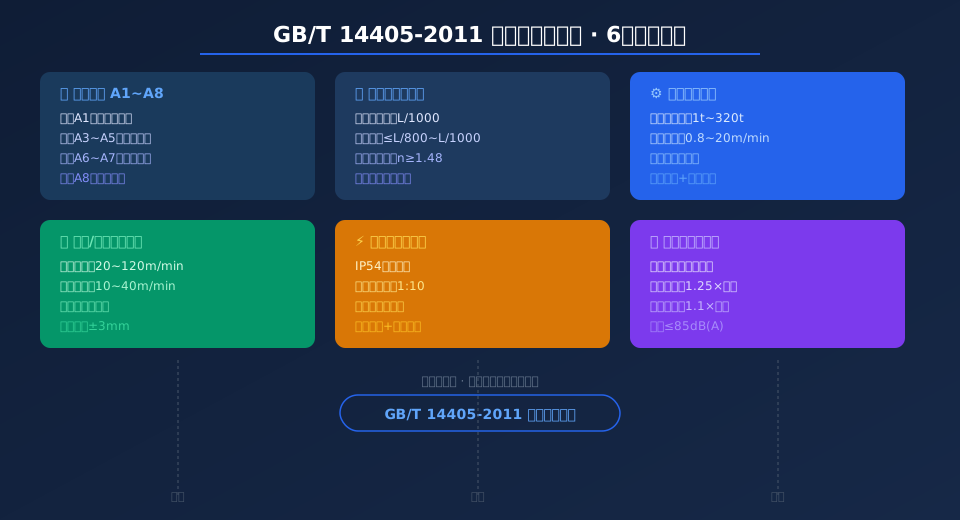
Standard Summary: GB/T 14405-2011 "General Purpose Bridge Cranes" specifies the complete acceptance framework for overhead cranes ranging from 1t to 320t, covering type parameters, technical requirements, test methods, inspection rules, and marking, packaging, transport, and storage. This standard applies to general purpose bridge cranes equipped with hooks, grabs, lifting magnets, and dual- or triple-purpose configurations. Cranes are classified into eight work duty classes from A1 to A8, spanning light-duty maintenance applications through extra-heavy continuous handling operations. The five core acceptance criteria include structural strength and stiffness, hoisting mechanism performance, crane and trolley travel accuracy, electrical control system reliability, and safety protection device effectiveness.
General purpose bridge cranes are the most common material handling equipment in industrial facilities, widely used across machinery manufacturing, metallurgy and foundry, warehousing and logistics, and power generation. As the governing standard for bridge crane product acceptance in China, GB/T 14405-2011 "General Purpose Bridge Cranes" has served as the primary basis for technical agreements and factory acceptance testing between manufacturers and end users since its implementation. Kelude Heavy Industry designs and factory-tests its QD, QDZ, and QDY series bridge cranes in strict compliance with this standard.
The standard comprehensively covers crane model designation rules, basic parameter series, complete machine technical requirements, safety protection device configuration, coating and anti-corrosion specifications, product nameplate requirements, and accompanying documentation. In particular, the technical requirements in Chapter 4 and the test methods in Chapter 5 form a complete closed loop for factory acceptance testing of bridge cranes.
Work Duty Classification & Load Spectrum: Eight Classes for Every Application
The work duty classification of a bridge crane is determined by two dimensions: utilization class (U0–U9) and load spectrum (Q1–Q4), resulting in eight duty classes from A1 to A8. This is the most critical parameter during crane selection, as it directly affects the design safety factor of the steel structure and the component configuration level.
Classes A1 through A2 are suitable for light-duty applications such as maintenance platforms and equipment installation where lifting is infrequent, with lifting speeds typically below 2 m/min.
Classes A3 through A5 correspond to medium-duty applications in machine shops and assembly lines — the most commonly shipped configuration from Kelude Heavy Industry. Hoisting mechanisms in this range are driven by YZR wound-rotor motors or YZP variable-frequency motors.
Classes A6 through A7 are intended for heavy-duty applications such as metallurgy, foundry, and scrap handling, requiring dual braking systems and hoisting mechanisms rated at least M6.
Class A8 covers extra-heavy continuous handling at ports and steel mills, with a minimum design service life of 32,000 hours.
Per GB/T 3811-2008 "Crane Design Standard", the work duty classification must be calibrated against actual annual operating hours, load spectrum factor, and total number of duty cycles — not estimated by experience alone. When preparing crane selection proposals, Kelude Heavy Industry collects detailed operational data from the customer's facility, including daily lift count, average load ratio, and annual working days, then uses load spectrum analysis software to recommend the appropriate duty class.
Structural Strength & Stiffness: Camber and Static Stiffness Control
Static stiffness of the main girder is the most direct indicator of a bridge crane's load-bearing performance. GB/T 14405-2011 specifies that when the rated load is applied at mid-span, the vertical static deflection at mid-span must not exceed 1/800 of the span (for classes A1 through A3) or 1/1000 of the span (for classes A4 through A8). This value is verified during the complete machine static load test using a theodolite or laser distance sensor.
The main girder camber must be between 0.9/1000 and 1.4/1000 of the span. This design intent is to compensate for deflection under self-weight and applied loads, keeping the trolley runway rail essentially level under full-load conditions. Local stability of the main girder web plate must be verified using the methods in the appendix of GB/T 3811-2008. When the web plate height-to-thickness ratio exceeds the specified limit, transverse or longitudinal stiffeners must be provided.
Kelude Heavy Industry manufactures its bridge crane main girders from Q355B low-alloy structural steel (≈S355JR). Large diaphragms are spaced at intervals not exceeding 1,500 mm inside the box girder, with transverse short stiffeners and longitudinal reinforcing angles on the web plates, ensuring structural rigidity under full-load conditions. Every crane undergoes a static load test at 1.25 times the rated load before shipment, with permanent deformation of the main girder limited to no more than 1/2000 of the span.
Hoisting Mechanism: Redundant Safety with Dual Braking & Overload Protection
GB/T 14405-2011 imposes a series of mandatory safety requirements on the hoisting mechanism.
First, wire rope safety factor: For hoisting mechanisms rated A1 through A5, the minimum wire rope safety factor must not be less than 5.0. For classes A6 through A8, it must not be less than 6.0. Line-contact or surface-contact wire rope constructions are preferred for improved fatigue resistance.
Second, redundant braking configuration: Bridge cranes used for handling molten metal or hazardous materials must be equipped with two independently operating brakes on the hoisting mechanism. Each brake must individually provide sufficient braking torque to safely hold 1.25 times the rated load.
Third, height limiting and overload protection: The hoisting mechanism must be fitted with a lifting height limit switch (counterweight-type or rotary-type) and a load-lowering height limiter, which automatically cut power and apply the brake before the hook reaches its upper or lower travel limits. The overload limiter must have a combined error no greater than ±5%, issuing a pre-warning signal at 90% of rated load and cutting off the hoisting circuit at 105%.
Kelude Heavy Industry's standard configuration uses Schneider or Siemens PLCs as controllers, combined with load cells and encoders for closed-loop control. Every safety protection device is individually subjected to simulated action testing before shipment to ensure functional reliability.
Travel Mechanisms & Rail System: Tolerance Control for Smooth Operation
The crane travel mechanism moves longitudinally along the runway rails, while the trolley travel mechanism moves transversely on the main girder rails. The travel accuracy of both directly determines handling stability and positioning accuracy. GB/T 14405-2011 requires that the span deviation of the crane runway rails not exceed ±5 mm, and that the difference in rail top surface elevation not exceed 1 mm over any 2 m of measured length.
The trolley rail gauge deviation must not exceed ±3 mm, and the relative elevation difference between the two rail top surfaces must not exceed 5 mm over the full length of the main girder. Travel mechanisms use either centralized or individual drive configurations. Modern bridge cranes commonly use individually driven geared motor units (all-in-one), controlled by VFDs for smooth starting and speed regulation, with starting acceleration not exceeding 0.2 m/s² to prevent noticeable load swing.
Kelude Heavy Industry equips its bridge crane travel mechanisms with SEW-Eurodrive or FLENDER geared motor units as standard. Control options include cam controllers, console joysticks, and wireless remote control, with positioning accuracy of ±10 mm to meet precision assembly station requirements.
Electrical System & Safety Protection: Five-Level Protection from Power Supply to Control
The electrical system of a bridge crane must withstand harsh industrial environments including high temperatures, dust, and vibration. GB/T 14405-2011 requires electrical cabinets to have a protection rating of at least IP54. All terminal blocks must be copper with anti-loosening treatment, and the main power circuit must include a main circuit breaker and branch circuit breakers to form a tiered protection system.
The safety protection system consists of five levels.
Level 1 — Main power protection: Includes the main disconnect switch, main circuit breaker, and undervoltage protection, ensuring the crane cannot restart automatically after a power interruption.
Level 2 — Short-circuit and overload protection: Each mechanism's motor circuit is individually protected by a thermal overload relay or electronic motor protector, with overload protection set points at 105%–125% of rated current.
Level 3 — Travel limit protection: Both crane and trolley travel mechanisms are equipped with two-stage travel limit switches — the first stage for deceleration and the second for stopping. Buffers at the ends absorb residual kinetic energy.
Level 4 — Emergency stop: Red emergency stop buttons are provided at the operator cab, floor operating station, and wireless remote control. Pressing any of these cuts power to all mechanism drives.
Level 5 — Safety monitoring: In accordance with the latest requirements of TSG 51-2023 Crane Safety Technical Supervision Regulation, bridge cranes with a rated lifting capacity above 50 t or a work duty class of A6 or higher must be equipped with a Safety Monitoring and Management System that records parameters such as load, torque, travel position, and brake status in real time, with data retention of no less than 30 days.
During on-site installation and commissioning, Kelude Heavy Industry tests the response time and operational reliability of all five protection levels item by item, and delivers an electrical safety test report to the customer for record-keeping.
Related reading:
GB/T 3811-2008 "Crane Design Standard"
GB/T 28757 "Bridge and Gantry Crane Terminology" Standard Interpretation
AS 2550.5 "Safe Use of Bridge and Gantry Cranes" Standard Interpretation
AS 1418.5 "Bridge and Gantry Cranes — Specific Requirements" Standard Interpretation
Bridge Crane Parameter Comparison by Work Duty Class
Kelude Heavy Industry: Overhead Crane & Gantry Crane Solutions
Kelude Heavy Industry specializes in the design, engineering, and manufacturing of high-performance overhead cranes and gantry cranes. Our product range covers a diverse array of industrial applications, from single-girder and double-girder bridge cranes to versatile gantry systems and specialized explosion-proof configurations. We provide complete material handling solutions tailored to enhance operational efficiency and safety in workshops, warehouses, and production facilities.
Key Clauses of GB/T 14405-2011 for Factory Tests and Acceptance
| Standard Clause | Test Item | Acceptance Indicator |
|---|---|---|
| 5.2 No-Load Test | All Mechanisms Throughout Operation | No Jamming/Abnormal noise/Creeping |
| 5.3 Static load test | 1.25multiples of rated load Hovering10min | Permanent Deformation≤L/2000 |
| 5.4 Dynamic Load Test | 1.1multiples of rated load Reciprocating Motion | All Mechanisms Function Normally |
| 5.5 Noise Testing | Cabin / Operator Caband Floor1.5mLocation | ≤85dB(A) |
| 4.8 Safety Device | Limit Switch/Overload/E-Stop Activation Item by Item | Cut Off Corresponding Circuit≤0.1s |
| 4.10 Coating / painting Inspection | Paint Film Thicknessand Adhesion | Total Film Thickness≥120μm |
Bridge Crane Acceptance Testing: Key Data at a Glance
Lifting Capacity Range
1t~320t
Hook / Grab / Electromagnetic series
Span Range
7.5m~31.5m
Increments of 3m
Work Duty Classification
A1~A8
8 levels covering all duty cycles
Static Load Test Load
1.25×Gn
Held for at least 10 minutes
Wire Rope Safety Factor
5.0~6.0
Increases with duty classification
Main Girder Static Stiffness
≤L/800~1000
Max deflection under full load
Frequently Asked Questions
Q: What is the practical difference between A3 and A5 work duty classifications for overhead cranes?
A: A3 and A5 both fall within the intermediate duty range, but they differ significantly in usage frequency and load factor. The A3 classification is designed for a total of approximately 63,000 duty cycles, making it suitable for maintenance workshops or spare parts warehouses with up to 2 hours of lifting per day and an average load factor below 50%. The A5 classification, by contrast, is rated for roughly 250,000 duty cycles and suits two-shift machining and assembly production lines with an average load factor around 63%. When selecting components, the hoisting mechanism motor power for a A5 crane is typically one to two frame sizes larger than that of a A3 unit of the same capacity, and the gearbox is correspondingly upsized to ensure adequate thermal balance for continuous operation. Kelude recommends opting for the A5 classification when duty conditions are uncertain. While this adds approximately 8%–12% to the initial investment, it eliminates the need for future structural reinforcement and mechanism replacement if the duty classification must be upgraded.
Q: What are the specific static load test requirements for overhead cranes under ISO 4306?
A: Clause 5.3 of the standard specifies a static load test at 1.25 times the rated lifting capacity. The trolley is positioned at mid-span, and the load is lifted 100mm–200mm off the ground and held for at least 10 minutes. After unloading, the permanent deformation at mid-span is measured and must not exceed 1/2000 of the span L. For example, a crane with a 22.5m span must show no more than 11.25mm of permanent deflection. The test is repeated three times, and no visible cracks, weld seam failures, loosened bolts, or permanent structural deformation are permitted. Following the test, the main girder camber must still fall within the design range of 0.9L/1000 to 1.4L/1000. Kelude performs a 1.25× static load test on every crane before shipment and issues a full inspection report, with test data archived for long-term reference.
Q: How do I resolve wheel rail gnawing and abnormal noise during bridge travel?
A: Wheel rail gnawing is one of the most common operating faults in overhead cranes. It manifests as severe friction between the wheel flange and the side of the crane rail during bridge travel, accompanied by a sharp screeching noise and metal flakes peeling off the rail surface. Follow these troubleshooting steps: First, re-measure the rail span deviation using a theodolite. ISO 4306 requires a tolerance of no more than ±5mm; if exceeded, adjust the rail clamps or re-secure the rail. Second, check the rotational speed synchronization of the two bridge drive motors. Mismatched VFD parameter settings can cause a travel speed difference between the two sides, so recalibrate the frequency reference signals on the inverters. Third, inspect the wheel diameters. A diameter difference exceeding 0.5mm between wheels on the same side of the crane creates a speed differential that leads to flange rubbing; the wheels must be re-turned or replaced. Kelude's after-sales team recommends installing an automatic rail lubrication system that sprays aTrace graphite-based lubricant onto the wheel flanges every 8 hours, which can reduce flange wear by more than 50%.
Q: How much does a 10-ton overhead crane with a 22.5m span cost?
A: The market reference price for a QD Type overhead crane with hook, rated at 10t×22.5m and built to A5 standard, ranges from $12,600 to $20,000 (excluding rail and installation). The price variance mainly comes down to the following configuration choices: hoisting motor brand (domestic YZR series accounts for roughly 12% of the total price, while imported SEW-Eurodrive or ABB motors add about $3,000–$4,400); control method (pendant control is standard, adding a wireless remote control costs $600–$900, and an operator cab adds $2,200–$3,700); variable-frequency speed control (VFD for hoisting only adds about $1,200, while full variable-frequency drive for both crane bridge and trolley adds approximately $3,000). Additionally, the rail system (P24–P43 crane rail + rail clamps + conductor rail/busbar) and installation & commissioning are typically quoted separately—for a 22.5m span, this totals roughly $3,700–$5,900. Kelude Heavy Industry offers free on-site surveying and selection scheme design. The quotation includes 17% VAT and one set of spare parts, with a standard delivery time of 25–35 working days after contract signing.
