

JIS B 8802:2018 Bridge Crane Manufacturing: 6 Acceptance Criteria
Standard Summary
JIS B 8802:2018 is the manufacturing standard for overhead cranes (bridge cranes) issued by the Japanese Industrial Standards Committee (JISC), designated as "Overhead Crane—Manufacturing Standard" (Crane — Manufacturing Standard). It specifies full-chain manufacturing technical requirements covering material selection, welding procedures, machining accuracy, assembly and commissioning, and protective coating. Together with JIS B 8801 (Structural Standard) and JIS B 8803 (Inspection Standard), it forms the three pillars of Japan's overhead crane standard system. This standard applies to the manufacturing of electric overhead traveling (EOT) cranes with a rated lifting capacity of 1t to 500t, and serves as the core manufacturing basis for Japanese crane manufacturers and products exported to the Japanese market.
JIS B 8802 Scope and Applicability for Overhead Cranes
Japan's overhead crane manufacturing industry holds a significant position in the global special equipment sector, with its manufacturing standard system centered on the JIS B 8800 series. JIS B 8802:2018, as the "Manufacturing Standard" of this series, was most recently revised and published by the Japanese Industrial Standards Committee in 2018, and is used in conjunction with JIS B 8801:2018 (Structural Standard), JIS B 8803:2018 (Inspection Standard), and JIS B 8804:2018 (Safety Standard).
This standard applies to the full manufacturing process of top-running electric overhead traveling cranes with rated lifting capacities from 1t to 500t, covering both single-girder and double-girder configurations. It does not cover special-purpose cranes such as explosion-proof, metallurgical-duty, or nuclear-facility cranes. Unlike China's ISO 4301 Crane Design Standard, which emphasizes design calculations, JIS B 8802 focuses on standardized control of manufacturing processes.
Material Management: Controlling Quality at the Source
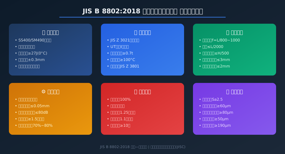
JIS B 8802 imposes strict material management requirements on structural steel. Steel plates for main girders and end carriages must use SS400 structural steel per JIS G 3101 or SM490 series structural steel per JIS G 3106, with a Mill Sheet system in place — each steel batch must be accompanied by third-party inspection reports for chemical composition and mechanical properties. The Charpy impact energy absorption for steel in critical load-bearing areas must not fall below 27J at 0°C, ensuring toughness reserves for low-temperature service conditions.
Steel plate thickness tolerance is controlled to within ±0.3mm of the nominal thickness, and the surface must be free from lamellar tearing, slag inclusion, and severe corrosion defects. Plates exceeding 40mm in thickness must undergo Ultrasonic Testing (UT) re-verification upon receipt, and may only be released for production after meeting Grade I acceptance criteria per JIS G 0801. Kelude Heavy Industry's manufacturing workshop strictly enforces this material admission system, eliminating weld seam cracking and structural fatigue issues caused by material defects at the source.
Welding Quality Control Under the JIS Z 3021 Symbol System
Welding is the most critical process in overhead crane manufacturing. JIS B 8802 references JIS Z 3021 (Welding Symbols) to standardize drawing annotations, requiring that the throat thickness of T-joint fillet welds between the main girder web plate and flange plates be no less than 0.7 times the thickness of the thinner plate, with an absolute minimum of 6mm. All load-bearing welds must be executed by welders holding JIS Z 3801 qualification certification, with the welder's certificate remaining valid and covering the applicable welding positions and plate thickness ranges.
Thick plates must be preheated to no less than 100°C before welding, with interpass temperature controlled between 100°C and 250°C. Critical butt welds on the main girder and box girder fillet welds must undergo Ultrasonic Testing (UT) 24 hours after welding completion, evaluated to Grade I per JIS Z 3060. Non-conforming areas must be ground out, re-welded, and re-tested until they pass. For heavy-duty cranes with a lifting capacity exceeding 50t, the butt welds on the main girder's tension flange must also undergo additional Radiographic Testing (RT) sampling inspection.
Welding Deformation Control reflects the refined workmanship of Japanese manufacturing: main girder welding must employ symmetrical welding sequences and back-step welding techniques. Post-weld side bow must be controlled within L/2000 (L = span). Components exceeding tolerance must be corrected by Flame straightening, operating within the heating temperature range (600°C~650°C) specified in the JIS B 8802 appendix, with strict prohibition of overheating that could degrade material properties.
Machining Accuracy: Main Girder Camber and Dimensional Tolerances
JIS B 8802 sets explicit requirements for the camber of overhead crane main girders: under no-load conditions, the mid-span camber f of the main girder must be maintained between L/800 and L/1000 (L = crane span), with the camber curve required to be smooth and continuous, free from local depressions or abrupt slope changes. This value is slightly higher than the minimum L/1000 requirement in China's TSG Q0002 Special Equipment Safety Technical Regulation for Lifting Appliances, reflecting the Japanese standard's higher pursuit of structural rigidity.
The perpendicularity deviation of the main girder web plate must not exceed 1/500 of the web height H, and the assembly gap between the cover plate and web plate must be controlled below 0.5mm. The diagonal difference of the end carriage wheel blocks (i.e., the difference in diagonal lengths between the two sets of wheels in the span direction) must not exceed 3mm. Both horizontal and vertical skew of wheels under the same end carriage must be controlled within L/1000, ensuring smooth crane travel without wheel rail gnawing. For crane projects exported to Japan, Kelude Heavy Industry employs laser tracker technology for full-line three-dimensional measurement, achieving assembly accuracy exceeding 1.2 times the JIS standard requirements.
Assembly, Commissioning, and Protective Coating
For mechanism assembly, JIS B 8802 requires that the shaft alignment error between the gearbox input shaft and the motor output shaft not exceed 0.05mm, with the coupling end-face clearance controlled between 2~4mm. The braking torque of the brake must reach at least 1.5 times the rated hoisting torque, and the contact area between the brake shoe and brake wheel must not be less than 80% of the design area. Grease fill volume at each lubrication point must be maintained at 70%~80% of the bearing cavity volume — either too much or too little affects heat dissipation and lubrication performance.
For protective coating, the steel structure surface must be Sandblasted to Sa2.5 (near-white) per ISO 8501-1, with surface roughness Rz controlled between 40~75μm. The coating system employs a three-layer protection scheme: Epoxy Zinc-Rich Primer (≥60μm) + Epoxy MIO Intermediate Coat (≥80μm) + Polyurethane Topcoat (≥50μm), with a total Dry Film Thickness (DFT) of no less than 190μm. After coating, the crane must be cured indoors for at least 7 days before shipment. During the No-Load Test Run, gearbox noise must not exceed 80dB(A), and the complete machine must operate smoothly without noticeable vibration. Every crane exported to Japan by Kelude Heavy Industry must pass full JIS B 8802 acceptance inspection before being released for shipment.
Material Requirements Comparison Table
| Material Category | JIS (Japanese Industrial Standards) B 8802Requirement | Corresponding Chinese Standard Reference |
|---|---|---|
| structural steel Plate | SS400/SM490(JIS (Japanese Industrial Standards) G 3101/3106) | Q235B (≈S235JR)/Q355B (≈S355JR)(GB/T 1591) |
| Impact Toughness | ≥27J (0°C, Charpy V-notch) | ≥27J (0°C or -20°C per Level) |
| Plate Thickness Tolerance | Nominal Thickness±0.3mm | per GB/T 709 BGrade Deviation |
| Heavy Plate UTRe-inspection | ≥40mmshall UT(JIS (Japanese Industrial Standards) G 0801 IGrade) | ≥40mmper GB/T 2970 IIGrade |
| Weld Material Matching | Equal Strength Matching(JIS (Japanese Industrial Standards) Z 3211/3212) | Equal Strength Matching(GB/T 5117/5118) |
| Material Certificate | Third Party Mill Sheet Full Batch | Mill Test Certificate+Incoming Re-inspection Sampling |
Welding and Inspection Requirements: A Side-by-Side Reference
| Inspection Item | JIS (Japanese Industrial Standards) B 8802Specification | Reference Standard Clause |
|---|---|---|
| Welder qualification | JIS (Japanese Industrial Standards) Z 3801Certification+Within Validity Period | JIS (Japanese Industrial Standards) B 8802 §5.2.1 |
| Preheating Temperature | ≥100°C(Plate Thickness>25mmwhen) | JIS (Japanese Industrial Standards) B 8802 §5.3.2 |
| Weld Seam Appearance | free from Crack/Undercut≤0.5mm/Reinforcement≤3mm | JIS (Japanese Industrial Standards) B 8802 §5.4.1 |
| UTFlaw detection | JIS (Japanese Industrial Standards) Z 3060 IGrade, Critical Weld Seam100% | JIS (Japanese Industrial Standards) B 8802 §5.4.3 |
| Static load test | 1.25times Rated Lifting Capacity, Load Holding≥10min | JIS (Japanese Industrial Standards) B 8802 §7.2.1 |
| Record Retention | Manufacturing Record Retention≥10years | JIS (Japanese Industrial Standards) B 8802 §8.3 |
8. Key Manufacturing Data at a Glance
Main Girder Camber
L/800–L/1000
Measured at mid-span, no load
Preheating Temperature
≥100°C
Minimum before welding thick plates
Total Coating Thickness
≥190μm
Three-layer protective system
Braking Torque Safety Factor
≥1.5×
Relative to rated hoisting torque
Wheel Diagonal Difference
≤3mm
Tolerance across end carriage span
Record Retention
≥10 years
Full traceability across manufacturing
9. Further Reading
JIS B 8821 "Crane Steel Structure Design Specification" – Standard Explained — Japanese standard covering allowable stresses and section selection for crane steel structures, used alongside JIS B 8802 for fabrication.
JIS B 8801 "Overhead Crane Design Specification" – Standard Explained — Core structural standard for Japanese overhead cranes, defining structural design and safety device requirements.
ISO 4301 Crane Design Standard: 9 Load Combinations and Work Duty Selection from M1 to M8 — China's fundamental crane design standard, offering a useful comparison with the Japanese JIS design approach.
International Standards FAQ Hub: Five Major Standard Systems Compared — One-stop comparison of ISO, FEM, ASME, JIS, and DIN.
Frequently Asked Questions
Q: What is the difference between JIS B 8802 and JIS B 8801 in manufacturing?
A: JIS B 8801 (Structural Standard) focuses on structural design and safety calculations — covering load combinations, allowable stresses, stability checks, and other design-level requirements. JIS B 8802 (Fabrication Standard), on the other hand, governs manufacturing process execution — from incoming steel inspection, welding procedures, and machining accuracy to coating protection across the entire production chain. The relationship is similar to the division between China's ISO 4301 design standard and the JB/T manufacturing standard series: 8801 addresses "is the design correct," while 8802 addresses "is the fabrication sound."
Q: What specific requirements does JIS B 8802 impose on welding procedure qualification?
A: Clause 5.2.2 of JIS B 8802 requires that all load-bearing weld seams be covered by a Welding Procedure Qualification Record (WPQR) before production welding begins, in accordance with JIS Z 3040. The qualification scope includes verification of base metal–filler metal combinations, confirmation of preheating and interpass temperatures, coverage of welding positions (flat, vertical, overhead), and mechanical property testing (tensile strength ≥ lower limit of base metal tensile strength, 180° bend with no cracks, impact toughness ≥ 27J). The WPQR must be signed off by a third-party inspector before it can be used in production.
Q: What should be done if the main girder camber of an overhead crane for export to Japan does not meet the required tolerance?
A: If the measured camber falls below the L/800 lower limit required by JIS B 8802, flame straightening can be used to correct it — select 3 to 5 heating points along the lower edge of the web plate, heat with a neutral oxy-acetylene flame to 600°C–650°C (dark cherry red), with a heating tape width of 30–50mm. After cooling, the camber can typically recover by L/2000 to L/1500. The girder must be allowed to cool slowly to room temperature — quenching with water is prohibited — and re-inspected by UT flaw detection to confirm no new cracks have formed. If the camber is still out of tolerance after the first correction, a second attempt may be made after a minimum 24-hour interval, but the total number of heating cycles must not exceed three. Kelude's fabrication team has accumulated extensive camber control experience through export projects to Japan, using pre-stressed reverse-deformation welding techniques at the factory to fundamentally prevent camber deviation.
Q: How long does a JIS B 8802 coating system last before peeling?
A: Under the three-coat system specified in JIS B 8802 (Epoxy Zinc-Rich Primer ≥60μm + Epoxy MIO Intermediate Coat ≥80μm + Polyurethane Topcoat ≥50μm), the service life in a typical industrial atmospheric environment (Corrosion Grade C3) is 8–12 years without substrate corrosion. In coastal high-salt environments (Grade C4–C5), we recommend adding an extra coat of Epoxy MIO Intermediate Coat to reach 120μm and increasing the Polyurethane Topcoat to 80μm, which extends the lifespan to 10–15 years. For routine maintenance, an annual inspection of coating integrity, with prompt touch-up painting of any damaged areas, is sufficient to prevent localized corrosion from spreading.
