

Overhead Crane Design & Manufacturing Standards: GB/T 3811 and 5905
The full lifecycle of overhead crane design and manufacturing is governed by seven core national standards, including GB/T 3811, GB/T 28264-2017, and GB/T 5905, covering structural design, electrical drives, safety monitoring, testing and validation, and welding quality. This article provides a structured compliance roadmap for each standard, serving as a technical navigation guide for crane design and manufacturing.
The design and manufacturing lifecycle of overhead cranes is strictly regulated by a multi-tier framework of national and industry standards, including GB/T, GB, JB/T, and NB/T. Drawing on years of product development and engineering practice, Kelude has systematically mapped the seven core national and industry standards that govern overhead crane design and manufacturing, along with their corresponding technical focus areas. This coverage spans the full compliance chain—from structural design and electrical drives to safety monitoring, testing and validation, and welding quality. This article serves as an introduction to the standard compliance series, offering a technical roadmap for the systematic interpretation of each standard clause. The applicable standards include GB/T 3811 Crane Design Standard, GB/T 12668.1-2017 Adjustable Speed Electric Drive Systems, GB/T 28264-2017 Safety Monitoring and Management System for Cranes, GB 5226.2 Electrical Safety of Machinery, GB/T 5905-2011 Crane Testing Specifications and Procedures, JB/T 13036 Technical Conditions for Anti-Sway Control of Cranes, and GB/T 5117 Carbon Steel Welding Electrodes.
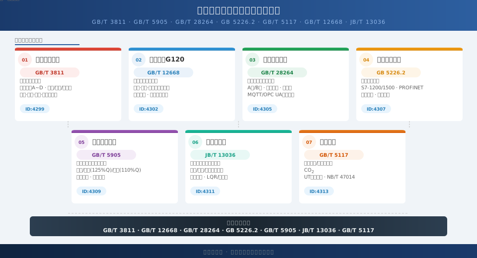
Quick Reference: Core Standards at a Glance
The table below summarizes the scope, standard level, and corresponding technical article for each of the seven core standards:
| No. | Standard No.. | Standard Name | Standard Level | Covered Topics | Article Link |
|---|---|---|---|---|---|
| 1 | GB/T 3811 Crane Design Standard-2008 | crane Design Specification | Recommended National Standard | Main Girder Structural Design | k/4299 |
| 2 | GB/T 12668.1-2017 | adjustable speed electric drive system | Recommended National Standard | Variable Frequency Speed Control G120 | k/4302 |
| 3 | GB/T 28264 Safety Monitoring and Management System-2017 | crane Safety Monitoring and Management System | Recommended National Standard | Safety Monitoring System | k/4305 |
| 4 | GB 5226.2 | Machinery Electrical Safety | Mandatory National Standard | Electrical Control System | k/4307 |
| 5 | GB/T 5905-2011 | crane Test Specificationand Procedures | Recommended National Standard | Load test Procedure | k/4309 |
| 6 | JB/T 13036 | craneanti-sway control Technical Specifications | Industry Standard | Anti-Sway Control | k/4311 |
| 7 | GB/T 5117-2012 | Carbon Steel Welding Electrode/Submerged Arc Welding Specification | Recommended National Standard | Welding Process | k/4313 |
Main Girder Design and GB/T 3811 Compliance
Overhead Crane Main Girder Design: A Complete FEA Guide provides a systematic interpretation of GB/T 3811, the governing standard for crane design. As the top-tier standard, it defines load classifications and combinations (Load Cases A through D), structural verification methods for strength, stiffness, and stability, as well as fatigue life assessment criteria. The article details the selection rationale for four main girder cross-sections—box girder, I-beam, truss girder, and cellular girder—under GB/T 3811 load conditions. It offers specific calculation methods for Load Case A (dead weight + lifting load), Load Case B (in-service wind load + inertial forces), Load Case C (out-of-service wind load + buffer collision forces), and Load Case D (installation/dismantling loads + seismic loads). The FEA section uses a 20t-22.5m QD-type overhead crane as a case study, demonstrating shell element modeling, meshing strategies, and the application of the 8 calculation scenarios specified by GB/T 3811, validating that the deviation between theoretical calculations and FEA results remains within 5% for engineering accuracy.
Key compliance points include: 1) Q235B main girder material with yield strength σs≥235MPa, safety factor n of 1.5~1.7, and allowable stress [σ]=138~157MPa; 2) Mid-span deflection limit of L/700 (for work duty A5~A6) or L/1000 (for A7~A8); 3) Verification methods for horizontal stiffness limit H/2000 and torsional stiffness limit of 0.003° per meter. The article also covers construction details such as the maximum opening ratio of 50% for cellular girders and stiffener spacing not exceeding twice the web plate height. The provided load calculation tables and section property tables are directly applicable for engineering design and selection.
VFD Drive Systems and GB/T 12668 Compliance
Crane VFD Drive System Selection and Parameter Configuration: An Engineering Guide details the design of variable-frequency drive systems in full compliance with the GB/T 12668 series standard for adjustable speed electric drive systems. Specifically, GB/T 12668.1-2017.2 specifies the ratings, operating conditions, and performance requirements for low-voltage AC variable-frequency drives, directly influencing the selection of VFDs for hoisting mechanisms subject to frequent starts/stops and heavy-load lifting. Using the Siemens G120 drive as a reference, the article covers the complete design process for the hoist, bridge, and trolley mechanisms, including main circuit reactor selection (input reactor ≥2% voltage drop, output reactor ≥3% voltage drop), braking unit and braking resistor power calculations (hoist braking power Pbr≥1.5Pm), parameter tuning for sensorless vector control (SLVC), and precise logic configuration for hoist brake control timing.
Standard compliance focuses on: 1) A rated current selection for crane-duty VFDs with a 1.2~1.5 times overload margin as per GB/T 12668.1-2017.4; 2) Braking resistor temperature rise not exceeding the insulation class limit specified in GB/T 12668.2 (Class F ΔT≤100K); 3) EMC compliance with the conducted and radiated emission limits of GB/T 12668.3. The article includes a VFD selection table for the three mechanisms of a 20t QD-type crane and a main circuit configuration diagram, serving as a direct reference for engineering projects.
Safety Monitoring System and GB/T 28264 Compliance
Crane Safety Monitoring and Management System: A Guide to GB/T 28264 focuses on the standardized construction of crane operational safety. GB/T 28264-2017, the mandatory national standard for crane safety monitoring and management systems, requires that all overhead and gantry cranes with a rated lifting capacity greater than 10t be equipped with a Safety Monitoring System. The article explains the two configuration levels: Level A (monitoring all parameters + data logging + remote transmission) and Level B (monitoring key parameters + data logging). It outlines a standard four-layer architecture design comprising the sensor layer, control layer, data processing layer, and display layer. Key compliance parameters include: Lifting Capacity Limiter accuracy of ±5%, Hoisting Height Limit Switch repeatability of ±20mm, Travel Limit Switch accuracy of ±50mm, and travel mechanism speed detection accuracy of ±2% FS.
Other mandatory GB/T 28264 compliance metrics for system architecture design include: 1) Black box data recording duration ≥72 hours with a sampling interval ≤2 seconds; 2) System power-off data retention ≥72 hours; 3) Alarm information storage capacity ≥5000 entries; 4) Brake door interlock using a normally closed contact safety circuit design, ensuring fail-safe operation. The article also discusses standard configuration methods for MQTT/OPC UA protocols for remote data transmission, fulfilling the functional requirements for remote monitoring interfaces as per GB/T 28264.
Electrical Control System and GB 5226.2 Compliance
Overhead Crane Electrical Control System: Complete Design Workflow details a system design process fully compliant with GB 5226.2, the mandatory standard for electrical safety of machinery. This standard stipulates clear requirements for safety protection, control circuit redundancy, insulation class, and earthing protection in crane electrical systems. The article follows a four-layer design methodology: main circuit diagram, control circuit diagram, PLC I/O wiring diagram, and safety circuit diagram. It includes selection calculations for PLCs (with a comparison table for S7-1200 and S7-1500), VFDs, HMIs, Lifting Capacity Limiters, and encoders. PLC programming employs a structured approach, providing program flowcharts for key function blocks such as hoist control, safety protection, and fault diagnosis. The safety circuit design strictly adheres to Chapter 9 of GB 5226.2, specifying hard-wired dual-channel redundant safety circuits, a minimum contact gap of ≥3mm for Emergency Stop Buttons, and a monitoring scheme for door interlock switches.
Key GB 5226.2 compliance review points: 1) Insulation resistance ≥1MΩ (measured with a 500V Megohmmeter); 2) Dielectric test at 1500V for 1 minute without breakdown or flashover; 3) Control system safety integrity level (SIL) not lower than SIL 2 (referencing IEC 62061); 4) Electrical cabinet Protection Rating not lower than IP 54; 5) Earthing circuit impedance ≤0.1Ω.
Load Testing Procedures and GB/T 5905 Compliance
Crane Load Testing and Type Testing: A Detailed Guide is based on GB/T 5905, the standard for crane test specifications and procedures, and TSG Q0002, the regulation for type testing of lifting appliances. It systematically defines the complete testing methodology, from No-Load Test to Type Test. GB/T 5905, derived from ISO 3165, holds universal authority in both domestic and international crane inspections. The article breaks down the four standard test scenarios: No-Load Test (all mechanisms operate without load for 30 minutes without abnormality), Rated Load Test (all mechanisms operate in conjunction at 110% of rated load for 1 hour), Static Load Test (a 125% rated load is lifted 100~200mm off the ground and held for 10 minutes; main girder deflection ≤L/700 is considered a pass), and Dynamic Load Test (all three mechanisms operate in conjunction at 110% rated load, with the hoisting mechanism performing 6 full lift/lower cycles and the bridge/trolley mechanisms completing 3 full travel cycles).
Standard compliance acceptance criteria: 1) Residual deformation of the main girder after the Static Load Test ≤0.5‰ of the span; 2) Brake temperature rise ≤ Class F limit (ΔT≤100K); 3) Hoisting mechanism brake slippage ≤100mm (under rated load); 4) Impact allowance for the Dynamic Load Test φ=1.05~1.1 (referencing GB/T 3811). The article also provides a complete pre-test preparation checklist (21 inspection items) and a Test Report template.
Anti-Sway Control and JB/T 13036 Compliance
Crane Anti-Sway Control: Principles and Engineering Implementation references the industry standard JB/T 13036 for crane anti-sway technology, systematically comparing the open and closed-loop technical paths of three mainstream anti-sway control solutions. JB/T 13036 specifies the allowable sway amplitude limits for cranes operating at rated speed and defines performance testing methods for anti-sway systems, serving as a common technical benchmark. Starting from the single-pendulum dynamic equation, the article derives formulas for calculating the sway period for different rope lengths. It provides parameter tuning tables for open-loop input shaping (ZV/ZVD/ZVDD third-order shapers) and pole placement design methods for a closed-loop state observer LQR. A technical comparison of the three solutions is presented: open-loop solutions achieve stabilization time ≤2s (for rope length L≤10m), the closed-loop LQR solution achieves residual sway amplitude ≤2mm, and the adaptive MRAC solution offers robustness of ±30% to variations in rope length.
JB/T 13036 compliance test requirements: 1) After braking from rated speed, the residual sway amplitude of the load ≤1‰ of the rope length; 2) With the anti-sway system active, the settling time for the load sway to decay to 5% of its initial amplitude ≤3 sway periods; 3) System response delay ≤50ms (PLC scan cycle). The article also introduces MATLAB Simulink simulation verification methods and on-site calibration procedures, covering hardware selection standards for encoders (accuracy ±0.1°) and inclination sensors (accuracy ±0.05°).
Welding Procedures and GB/T 5117 / NB/T 47014 Compliance
Crane Main Girder Welding Procedure and Weld Seam Quality Control: The Complete Guide is built on three foundational standards: GB/T 5117 for carbon steel electrodes, NB/T 47014 for welding procedure qualification of pressure equipment, and GB/T 11345 for ultrasonic testing of welds. As the primary load-bearing component of an overhead crane, the design and workmanship of the main girder's longitudinal fillet welds and stiffener welds directly determine overall machine safety. This article specifies the electrode selection and matching scheme: Q235B base metal paired with E4315 electrodes (tensile strength ≥420MPa), Q345B base metal paired with E5015 electrodes (tensile strength ≥490MPa). Two welding procedure options are detailed—gas-shielded welding (wire ER50-6, φ1.2mm) and submerged arc welding (wire H08MnA with SJ101 flux)—each accompanied by parameter tables covering welding current, arc voltage, travel speed, and gas flow rate.
Key weld quality control criteria: 1) Visual inspection of weld seams per GB/T 12469 Grade II, with no cracks, lack of fusion, or undercut exceeding 0.5mm in depth; 2) 100% ultrasonic testing in accordance with GB/T 11345, acceptance level Grade I; 3) Welding deformation control through symmetrical welding sequence, backstep welding, and preforming (counter-deformation of 1‰–1.5‰ of girder length), with total main girder length deviation held to ≤±10mm after welding; 4) Welding procedure qualification records (WPQR) and Welding Procedure Specifications (WPS) developed per NB/T 47014. The article also includes a reference atlas of common weld defects in crane main girder fabrication along with rework procedures.
Standard Framework Comparison for Crane Welding
The table below compares seven standards across four dimensions—standard hierarchy, mandatory status, applicable scope, and implementation phase—to help design, fabrication, and inspection personnel quickly determine which standard applies to their specific task:
| Standard No.. | Standard Level | Mandatory Level | Applicable Objects | Implementation Stage |
|---|---|---|---|---|
| GB/T 3811 Crane Design Standard-2008 | National Standard (Recommended) | Recommended | Overall Machine Design | Design Stage |
| GB/T 12668.1-2017 | National Standard (Recommended) | Recommended | Electric Drive | Design Selection |
| GB/T 28264 Safety Monitoring and Management System-2017 | National Standard (Recommended) | Mandatory Implementation | Electrical Safety Monitoring | Manufacturing and Installation |
| GB 5226.2 | Mandatory National Standard | Mandatory | Electrical Safety | Design+Manufacturing |
| GB/T 5905-2011 | National Standard (Recommended) | Recommended | complete machine test | Factory Acceptance Test |
| JB/T 13036 | Industry Standard | Recommended | Motion Control | Commissioning Stage |
| GB/T 5117-2012+NB/T 47014 | Recommended National Standard+Industry Standard | Recommended | Welding Manufacturing | Manufacturing Stage |
How to Apply the Overhead Crane Standard System
The most effective way to build a solid understanding of overhead crane standards is to follow the product lifecycle from design through manufacturing. Start with GB/T 3811 Crane Design Standard to establish structural design fundamentals and load calculation capabilities. From there, move to GB/T 12668 and GB 5226.2 for electrical drive and safety requirements, then use GB/T 28264 Safety Monitoring and Management System to integrate standardized monitoring concepts into your design. Next, apply GB/T 5905 and JB/T 13036 to master test verification and advanced control compliance, and finish with GB/T 5117 and NB/T 47014 to complete the manufacturing-stage standard framework. These standards are interconnected—for instance, GB/T 3811 and GB/T 5905 align on load coefficient values, forming a complete chain of compliance. Understanding how they reference each other gives you a systematic view of overhead crane design and manufacturing standards. Design, manufacturing, and inspection professionals can jump directly to the relevant section for their role.
