

Overhead Crane Main Girder Design & FEA: Load to Deflection
Overhead Crane Main Girder Design & FEA: Load Calculations to Deflection Checks. The main girder is the most critical load-bearing component of an overhead crane; its structural design directly determines the crane's lifting capacity, safety performance, and service life.
The main girder is the backbone of any bridge crane, carrying the full load and dictating the machine's overall capability, safety, and longevity. This guide walks through the complete structural design process for overhead crane main girders, covering six key stages: load calculation, section selection, strength verification, stiffness checks, stability analysis, and finite element analysis (FEA) validation. All procedures align with the requirements of ISO 4301 (Crane Design Standard) and FEM 1.001 (Crane Test Specifications and Procedures), providing a practical, step-by-step reference for design and engineering professionals.
Main Girder Types and Selection Criteria
Overhead crane main girders come in four common configurations: box girder, I-beam, truss girder, and cellular girder. The box girder—a closed section welded from top and bottom flange plates and two web plates—offers high torsional rigidity and uniform load distribution, making it the industry standard for general purpose bridge cranes with lifting capacities from 5t to 320t. I-beam girders, either rolled or welded, are simpler to manufacture and more cost-effective, making them ideal for light-duty cranes with capacities up to 10t and spans up to 15m. Truss girders, fabricated from angle steel or steel tubing into a spatial lattice structure, deliver excellent strength-to-weight ratios and low wind resistance, suiting them for long-span applications of 30m or more or where dead weight is a concern. Cellular girders feature regularly spaced hexagonal openings cut into the web of an I-beam, achieving greater section depth and bending stiffness for the same steel consumption—an efficient choice for medium spans of 15–25m where headroom is limited. When selecting a girder type, engineers must weigh lifting capacity, span, work duty classification, operating environment, and cost, then perform a multi-option technical and economic comparison in accordance with ISO 4301 before finalizing the design.
| Comparison Item | box girder | I-beam | Truss Girder | Castellated Beam |
|---|---|---|---|---|
| Lifting Capacity Scope | 5t~320t | ≤10t | ≤50t | ≤20t |
| Span Scope | Optional | ≤15m | ≥30m | 15~25m |
| Torsional Resistance Stiffness | Excellent | Fair | Poor | Good |
| Manufacturing Complexity | Moderate | Simple | Complex | Moderate |
| Dead Weight | Heavy | Light | Lightest | Lighter |
| Cost Comparison | Baseline | Low20%~30% | High15%~25% | Low10%~15% |
| Applicability Work Duty / Classification | A3~A8 | A1~A4 | A3~A6 | A3~A5 |
Main Girder Load Calculation
Box Girder Section Design and Optimization
Section design of the box girder involves determining geometric parameters such as girder depth, flange plate width and thickness, and web plate thickness. Girder depth is the key parameter affecting bending stiffness and dead weight. To meet stiffness requirements (deflection ≤ L/700 to L/1000, depending on the work duty) and clearance constraints, the girder depth is typically taken as 1/14 to 1/18 of the span. Flange plate width is set at 1/3 to 1/5 of the girder depth, with thickness determined so that flange stress does not exceed the allowable stress. Web plate thickness is governed primarily by shear strength and local stability; for webs without longitudinal stiffeners, the height-to-thickness ratio should not exceed 160–200. Stiffener arrangement must be considered concurrently with section design, including transverse stiffeners, longitudinal stiffeners, and short stiffeners, to prevent local buckling of the web and flange plates. Transverse stiffener spacing is generally 0.5 to 2.0 times the web height, and longitudinal stiffeners are placed at 1/5 to 1/4 of the web height from the compression flange.
Strength Verification
Strength verification of the main girder covers three aspects: normal stress, shear stress, and equivalent stress. Normal stress is checked at the mid-span section, where the maximum flange stress under combined vertical and horizontal loads must not exceed the allowable material stress. Shear stress verification focuses on the end sections, where the maximum web shear stress under combined trolley wheel loads and end carriage reactions must remain within the allowable shear stress. Equivalent stress verification applies to regions where both normal and shear stresses are significant (e.g., stiffener ends and quarter-span points), calculated using the von Mises criterion. Allowable stresses are determined per ISO 4301. For Q235B steel (≈S235JR) with a safety factor of n=1.48, the allowable tensile/compressive/bending stress is 160 MPa and the allowable shear stress is 95 MPa. For Q345B steel (≈S355J2), the corresponding values are 230 MPa and 135 MPa. For cranes in heavy and very heavy duty classifications, fatigue strength verification is also required, using the fatigue load spectrum and S-N curves per ISO 4301 to calculate cumulative damage factors.
Stiffness Verification
Stiffness verification of the main girder covers vertical static stiffness, horizontal stiffness, and torsional stiffness. Vertical static stiffness is measured by the maximum mid-span deflection under the rated lifting load, which must not exceed L/700 to L/1000 (L/700 for duty class A1–A3, L/800 for A4–A6, and L/1000 for A7–A8). Deflection calculations must account for both bending and shear deformation of the girder section; for relatively short spans (L/H < 10), the shear deformation effect cannot be neglected. Horizontal stiffness is checked for the lateral deflection of the girder under crane travel starting/braking or lateral forces, with a limit of L/2000. Torsional stiffness primarily affects smooth trolley travel and uniform wheel contact; for box girders with offset rail arrangement, the torsional angle is evaluated and must not exceed 0.5° under full load. Actual deflection can be verified through crane load testing in accordance with the test procedures specified in FEM 1.001, using displacement transducers or levels to measure mid-span deflection under rated load.
Stability Analysis
Girder stability comprises both overall stability and local stability. Overall stability refers to the girder's resistance to lateral-torsional buckling under load. stability and local stability. Overall stability refers to the girder's resistance to lateral-torsional buckling under load. For box sections, the relatively large spacing between the two webs generally ensures adequate overall stability; however, when the depth-to-width ratio is high (H/B > 2.5) or the flange width-to-thickness ratio is large, overall stability verification is mandatory. Local stability addresses the compression zones of the web and flange plates by dividing the plate regions into smaller panels through stiffeners. Web local stability is verified using the critical stress formulas given in ISO 4301 or through finite element eigenvalue buckling analysis. Flange local stability is ensured by limiting the width-to-thickness ratio: for Q235 steel, this ratio should not exceed 40, and for Q345 steel, it should not exceed 33. Finite element buckling analysis provides a more precise determination of the buckling mode and critical load, with a recommended buckling safety factor of no less than 1.5.
Finite Element Modeling and Simulation
Finite element analysis (FEA) serves as both a complement and a validation to traditional theoretical calculations, enabling a more precise evaluation of stress distribution and deformation characteristics in the main girder under complex loading conditions. In the modeling phase, the main girder is simulated using shell elements (Shell181 or S4R) for the flange plates and web plates, while solid elements represent the stiffeners and connection plates. The connection between the main girder and end carriages is modeled using rigid regions or contact elements. Mesh refinement is applied in stress concentration zones—such as stiffener ends, weld seams, and wheel load application points—with element sizes controlled between 10–20 mm, gradually transitioning to a coarser 30–50 mm mesh in less critical areas. Simply supported constraints are imposed at the girder ends, restricting displacement degrees of freedom at the end carriage connection nodes. Load applications include dead weight (via gravitational acceleration), fixed loads (uniformly distributed pressure), and moving loads (concentrated or uniformly distributed pressure applied at the trolley wheel load zones). Analysis outputs include total displacement contours, von Mises stress distributions, principal stress vector diagrams, and buckling mode shapes, which are used to verify maximum deflection locations, stress concentration areas, and potential instability regions.
Engineering Case Study: Design Validation in Practice
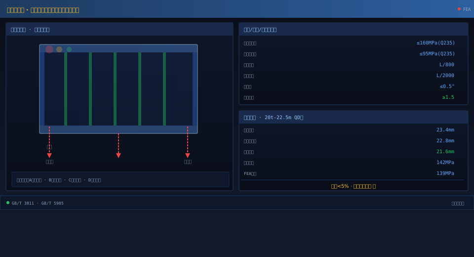
The complete design and validation workflow is demonstrated using a 20t-22.5m QD type bridge crane main girder as a case study. Design parameters: rated lifting capacity of 20t, span of 22.5m, work duty classification of A5, trolley dead weight of 7.5t, and trolley wheel base of 2.5m. Following cross-section optimization, the final main girder dimensions were established with a girder height of 1500mm, flange plate width of 520mm × 16mm, web plate thickness of 8mm, and transverse stiffener spacing of 1500mm. Theoretical calculations yielded a maximum mid-span deflection of 23.4mm (L/962), satisfying the A5 requirement of L/800. The maximum mid-span normal stress was calculated at 142MPa, below the Q235B allowable stress of 160MPa. Comparison between FEA results and theoretical calculations shows strong correlation: mid-span deflection of 22.8mm (2.6% deviation) and maximum stress of 139MPa (2.1% deviation). Prior to shipment, the prototype underwent rated load testing and a 1.25× static load test in accordance with FEM 1.001, with a measured mid-span deflection of 21.6mm—a 3.8% deviation from the theoretical value—further confirming the accuracy of the design and analysis methodology.
