

Siemens G120 VFD Selection & Parameter Setup for Overhead Cranes
A variable-frequency drive (VFD) system is the core electrical control equipment for stepless speed control of the hoisting, trolley, and crane travel mechanism mechanisms on an overhead crane. Proper drive selection directly impacts operational smoothness, energy efficiency, and equipment service life. This article uses the Siemens G120 VFD as an example, covering everything from selection criteria and main circuit design to parameter configuration.
A variable-frequency drive (VFD) system is the core electrical control equipment that enables stepless speed control for the hoisting mechanism, trolley mechanism, and crane bridge travel on an overhead crane. The correctness of drive selection and parameter configuration directly affects operational smoothness, energy efficiency, and equipment lifespan. Using the Siemens G120 VFD as the reference platform, this article provides a systematic walkthrough of drive selection criteria, main circuit design, parameter configuration, commissioning procedures, and maintenance essentials for crane VFD systems. It aligns with the GB/T 12668 standard for adjustable speed electric drive systems and addresses the specific demands of crane duty cycles, serving as a practical reference for electrical engineers.
VFD Operating Principle and Crane Duty Requirements
Variable frequency speed control adjusts the motor rotational speed by changing the stator supply frequency while simultaneously regulating voltage to maintain a constant flux (constant V/f ratio). This enables constant-torque speed control below rated speed and constant-power speed control above rated speed. The hoisting mechanism requires four-quadrant operation — motoring during hoisting and regenerative braking during lowering — which places explicit demands on the VFD's regenerative energy handling capability. The crane bridge travel and trolley mechanisms operate predominantly in the horizontal plane with frequent start-stop cycles, requiring smooth acceleration/deceleration and high positioning accuracy. When selecting a VFD for crane applications, the following parameters are critical: rated power should cover 1.1 to 1.3 times the motor rated power; overload capacity must satisfy the crane standard requirement of 150% rated current for 60 seconds; and the protection rating (IP) should be at least IP20 for indoor installations and IP54 for outdoor installations. The Siemens G120 series features a modular design with a separate CU control unit and PM power module, covering a power range from 0.37 kW to 250 kW. It includes built-in crane-specific function blocks (such as hoist brake control and anti-sway pre-processing), making it a mainstream choice for crane variable-frequency drive systems.
| Comparison Item | Hoisting mechanism | crane travel mechanism | trolley mechanism |
|---|---|---|---|
| Frequency Inverter / VFDModel | PM240-2 37kW | PM240-2 7.5kW×2 | PM240-2 4kW |
| Control Mode | SLVCVector Control | SLVC+Torque Master-Slave | SLVCVector Control |
| Acceleration Ramp Time | 3~4s | 5~8s | 2~4s |
| Deceleration Acceleration Ramp Time | 2~3s | 4~6s | 2~3s |
| Zero-Speed Holding Torque | 110%/1.5s | Not Required | Not Required |
| Braking Resistor | 14Ω/6kW Required | None | None |
| overload capacity | 150%/60s | 150%/60s | 150%/60s |
Main Circuit Design and Component Selection
The main circuit design covers the selection and configuration of the input reactor, braking unit, braking resistor, and output reactor. The input reactor suppresses grid harmonics and limits inrush current; its inductance is typically set to 2%–4% of the VFD's rated current. It is recommended that all crane VFDs be equipped with an input reactor. The hoisting mechanism must be fitted with a braking unit and braking resistor to dissipate regenerative energy produced during motor braking. The braking unit's conduction voltage is generally set to 1.15–1.2 times the DC bus voltage (approximately 760–790 V), while the resistance and power rating of the braking resistor are calculated based on the hoisting mechanism's potential-load characteristics, with the capacity designed for continuous operation of 30 minutes or more under the most severe condition (full-load lowering). The output reactor protects motor insulation from high-frequency harmonics on the VFD output side and is mandatory when the motor cable length exceeds 50 m. Circuit breakers or fuses should be sized at 1.5–2.0 times the VFD's rated input current. Contactors are recommended on the input side of the VFD to enable rapid power disconnection in the event of a fault.
Selecting the Right Control Mode for Crane Drives
Hoisting Mechanism Parameter Configuration
The hoisting mechanism is the most critical VFD application on a crane, and parameter configuration must focus on the following functions. Ramp times are determined by balancing operator comfort with productivity: typical hoisting acceleration time is 2–4 seconds with 2–3 seconds deceleration, while lowering uses 1–2 seconds for both acceleration and deceleration. The zero-speed torque function (zero-speed clamping or DC braking) prevents load slipping during brake release and brake application. It is recommended to set the holding time to 1–2 seconds and the holding torque to 100%–120% of the motor's rated torque. Brake control is the core of hoisting VFD configuration: the VFD's relay output controls the brake open/close sequence. Upon receiving a start command, the VFD first establishes excitation current and torque, then issues the brake-release command after a 0.3–0.5 second delay. During stopping, the VFD decelerates to zero speed, issues the brake-application command, and then blocks the pulses after a 0.1–0.2 second delay. Incorrect brake control logic can lead to load slipping or motor stall accidents. The regenerative braking function activates automatically when the motor speed exceeds the synchronous speed, with regenerative energy dissipated through the braking resistor. The braking unit's activation voltage is recommended to be set at 115% of the DC bus voltage (approximately 775 Vdc).
Crane Bridge and Trolley Travel Parameter Setup
The travel characteristics of the crane travel and trolley mechanisms differ from those of the hoisting mechanism: their loads are frictional rather than potential, and acceleration/deceleration primarily overcomes inertia. The bridge travel mechanism typically requires 20%–40% of the hoisting power, while the trolley mechanism requires 10%–20%, making the PM240 or PM250 power modules of the G120 drive sufficient. Ramp times are determined by the crane's travel distance and operating speed: for the bridge, acceleration is typically 4–8 seconds with 3–6 seconds deceleration; for the trolley, 2–4 seconds acceleration and 2–3 seconds deceleration. For multi-motor bridge drives (long-span cranes with two or four bridge drive motors), the G120's torque master-slave control function must be used: one drive is designated as the master (speed control), while the others operate as slaves (torque control), receiving the master's torque reference to ensure torque equalization across all drive wheels. The torque reference for slave drives is transmitted via analog output terminals or fieldbus communication. The anti-sway pre-processing function (Vibration Damping) reduces load swing during acceleration and deceleration by superimposing a compensating component onto the trolley's speed reference. This function requires encoder feedback.
Fieldbus Communication and PLC Integration
The G120 VFD integrates with the upstream PLC control system via the communication interface on the CU control unit. Supported protocols include PROFINET (recommended; 100 Mbps transmission rate, 1–4 ms cycle time), PROFIBUS DP (12 Mbps, 2–6 ms cycle time), and USS (serial, for commissioning and maintenance only). PROFINET configuration steps: import the G120's GSD file into TIA Portal, assign the device name and IP address, and configure the process data area (PKW + PZD). The hoisting mechanism typically uses 4 words of process data (control word, speed setpoint, status word, actual speed), while the crane travel and trolley mechanisms use 2 words (control word + speed setpoint). The control word bit assignments follow the PROFIdrive profile: bit 0 enables operation, bit 1 disables the ramp, bit 3 enables pulses, and bit 4 enables the ramp. Emergency stop and safety functions are connected to the PLC via hard wiring rather than through the fieldbus, ensuring compliance with ISO 13849 and EN 62061 safety standards.
Commissioning and Fault Diagnosis
Siemens Starter software (for non-TIA Portal projects) or TIA Portal Startdrive (integrated into the TIA Portal platform) is recommended for commissioning. The commissioning sequence is as follows: verify main circuit and control circuit wiring before power-up; confirm DC bus voltage is normal after power-up; set motor parameters and run motor identification; configure ramp times and limit parameters; perform no-load test runs (jog each mechanism to verify correct rotation direction); and conduct loaded test runs (progressively load the hoisting mechanism up to 110% of rated load, verifying current and temperature rise). Common faults and troubleshooting: F30021 (DC bus overvoltage) frequently occurs during full-load lowering — check the braking resistor resistance and braking unit conduction voltage; F30011 (motor overload) is often caused by overly short acceleration/deceleration times or incorrect brake control timing; F07086 (brake fault) requires checking the brake power supply and control wiring. The oscilloscope function in Starter software can capture current, speed, and torque waveforms during hoisting start/stop cycles, aiding in diagnosing dynamic performance issues.
Typical Application Configuration Example
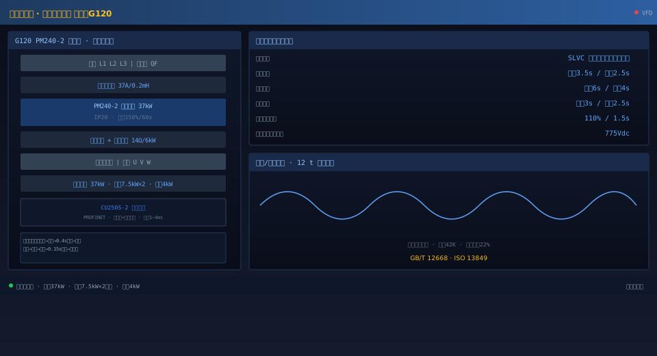
This article examines a VFD retrofit project on a 20t QD Type overhead crane. The hoisting mechanism is equipped with one G120 PM240-2 37kW power module paired with a CU250S-2 control unit, an input reactor rated at 37A/0.2mH, and a braking resistor rated at 14Ω/6kW (30% ED continuous duty). The crane travel mechanism uses two G120 PM240-2 7.5kW units in dual-motor master-follower configuration, while the trolley mechanism is powered by one G120 PM240-2 4kW unit. Ramp times are set to 3.5 seconds for hoisting, 6 seconds for crane travel, and 3 seconds for trolley travel. The hoisting drive maintains 110% holding torque at zero speed for 1.5 seconds, with a brake open delay of 0.4 seconds and a brake close delay of 0.15 seconds. Post-retrofit testing shows smooth motor current without surges during full-load hoisting, a VFD temperature rise of 42K (well below the 55K allowable limit), and a single-cycle temperature rise of the braking resistor kept within 180°C during full-load lowering. Overall system energy efficiency improved by approximately 22% compared to the original line-frequency operation scheme.
