

GB/T 28264 Crane Safety Monitoring System Guide
GB/T 28264 Safety Monitoring and Management System for Overhead Cranes: Standard Interpretation and System Architecture Design. The Safety Monitoring and Management System (SMMS) is a core technical safeguard for the safe operation of bridge and gantry cranes. Its design, configuration, and inspection must strictly comply with the national standard GB/T 28264 Safety Monitoring and Management System for Lifting Appliances.
The Safety Monitoring and Management System (SMMS) is a critical technology for ensuring the safe operation of overhead and gantry cranes. Its design, configuration, and inspection must follow the requirements of GB/T 28264, the national standard governing safety monitoring and management systems for lifting appliances. This article provides a systematic review of the standard's scope, technical requirements, functional configuration, and inspection rules, and offers practical guidance on system architecture design and equipment selection based on real-world engineering applications — serving as a complete technical reference for crane manufacturers and end users alike.
Scope of Application and Classification Requirements
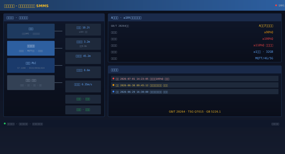
GB/T 28264, first issued in 2017 and replacing the 2012 edition, applies to safety monitoring and management systems used on various types of lifting appliances, including bridge cranes, gantry cranes, tower cranes, and mobile cranes. The standard classifies monitoring systems into two grades — Grade A and Grade B — based on the crane's rated capacity and hazard level. Grade A applies to applications requiring comprehensive monitoring, such as bridge and gantry cranes with a rated lifting capacity of 10 t or more, and ladle cranes with a rated lifting capacity of 5 t or more. Grade A systems must monitor at least seven safety parameters, including lifting capacity, hoisting height/load-lowering depth, travel distance, hoisting and trolley/traverse travel speeds, brake status of each mechanism, door limit switch status, and wind resistance and anti-skid status. These systems must also provide alarm, data recording, and remote transmission functions. Grade B applies to lifting appliances with a rated lifting capacity below 10 t and requires monitoring of at least three safety parameters: lifting capacity, hoisting height/load-lowering depth, and brake status of each mechanism. Both grades must be equipped with audible and visual alarm functions — when a monitored parameter exceeds its preset threshold, the system automatically triggers an alarm and displays and records the alarm event on the monitoring host.
| Comparison Item | AClass(≥10t) | BClass(<10t) |
|---|---|---|
| applicable tonnage | ≥10tBridge Gantry Crane | <10tlifting appliances |
| Detection Parameter | ≥7Comparison Item | ≥3Comparison Item |
| Lifting Capacity Detection | Mandatory | Mandatory |
| Lifting Height | Mandatory | Mandatory |
| Travel Distance | Mandatory | Optional |
| Travel Speed | Mandatory | Optional |
| Brake Status | Mandatory | Mandatory |
| Door Limit Switch Status | Mandatory | Optional |
| Remote Transmission | Mandatory | Optional Configuration |
| Data Storage | ≥1Months | ≥1Months |
System Architecture
Load Limiting and Overload Protection
The load limiter is the most critical subsystem in a crane safety monitoring system. Its performance directly determines the crane's overload protection capability. Per GB/T 28264 Safety Monitoring and Management System requirements, the load limiter must issue a pre-warning signal (audible and visual alarm with a yellow indicator) when the load reaches 90% of the rated lifting capacity, a continuous alarm (audible and visual with a red indicator) at 100% of rated capacity, and automatically cut power to the hoisting mechanism's upward direction at 110% of rated capacity while triggering an emergency alarm. Load sensors, typically resistance strain-gauge force sensors, are installed beneath the fixed pulley block support or under the drum bearing housing of the hoisting mechanism, with a measurement accuracy of no less than ±5%. The sensor signal is amplified by a transmitter and fed into the PLC's analog input module, where the sampled value is compared against calibration data to determine the current load. For hoisting mechanisms with dual-motor drives, signals from all hoisting branches are summed before evaluation. After an overload trip, the system must be manually reset before normal operation can resume.
Hoisting Height and Travel Distance Monitoring
Hoisting height monitoring prevents the lifting spreader or load from striking the upper limit. When the spreader rises to within 200 mm of the upper limit position, a deceleration warning is issued. If it continues to the limit position, power to the hoisting mechanism's upward direction is automatically cut and an alarm sounds. A multi-turn absolute encoder is the preferred height sensor, mounted on the hoisting drum shaft end. The spreader height is calculated from drum rotations using the formula H = n × π × D (where n is the number of drum revolutions and D is the drum diameter), with encoder resolution of no less than 4096 ppr. Travel distance monitoring tracks the trolley and crane bridge positions along the rails using incremental encoders combined with mechanical limit switches, or a non-contact gray-code bus positioning system. Terminal limit switches (typically bidirectional) are installed at the extreme ends of trolley and bridge travel. A deceleration warning is issued when the trolley or bridge comes within 2 m of the rail-end buffer stop, and travel power in that direction is cut off at 1 m from the stop. Travel data is also used for anti-collision control — an approach alarm is triggered when the distance between adjacent cranes on the same rail falls below the preset safety clearance.
Brake and Door Limit Switch Monitoring
Brake condition monitoring requires real-time detection of the hoisting mechanism brake's open and closed states. An alarm is immediately triggered and logged if the brake opens unexpectedly while the motor is stopped (brake failure) or closes unexpectedly while the motor is running (brake malfunction). Brake status sensors, either micro switches or inductive proximity switches, are mounted on the brake arm or push rod, with normally-closed contacts wired in series into the safety circuit. Any brake that fails to fully open or fully close triggers the safety protection. Door limit switch monitoring requires interlock switches on all access doors leading to the crane walkway and operator cab. When a door is open, crane travel power is cut and an alarm sounds, preventing personnel from entering hazardous areas while the crane is in operation. For outdoor cranes, the anemometer must be installed at the highest unobstructed point of the crane. When wind speed exceeds the allowable working limit (typically Beaufort scale 6–7, approximately 13.8–17.1 m/s), an alarm is triggered and the wind-resistant anti-slip device is automatically activated.
Data Logging and Remote Transmission
The safety monitoring and management system must provide data logging and export capabilities. Recorded data includes lifting capacity, hoisting height, travel distance, travel speed of each mechanism, cumulative operating hours per mechanism, alarm records (alarm type, time, and recovery time), and operator activity logs (operator ID and operating time windows). Industrial-grade SD cards or solid-state drives with a minimum capacity of 32 GB are recommended for data storage, with USB export support. Remote transmission is achieved via Ethernet or 4G/5G wireless communication modules, uploading safety monitoring data in real time to a remote management platform. MQTT or OPC UA are the recommended data transmission protocols. Uploaded content must include at minimum alarm information, real-time critical safety parameter values, and equipment operating status. The remote platform should be capable of receiving monitoring data from multiple cranes and presenting each unit's operating status and alarm statistics through a graphical interface.
Inspection and Acceptance
Inspection of the safety monitoring and management system is carried out in accordance with Appendices A and B of GB/T 28264, covering both factory acceptance testing and on-site inspection. Factory acceptance testing is completed at the manufacturing facility and includes functional testing of all sensors, alarm function tests, control output tests, data logging tests, and communication function tests. On-site inspection is performed at the crane installation site and covers installation position verification, wiring checks, system integration testing, alarm threshold calibration, and remote communication testing. Upon successful completion, an inspection report is issued containing the system configuration list, sensor calibration records, functional test results, and the inspection conclusion. Safety monitoring systems on cranes already in service must undergo periodic inspection once per year. This inspection is carried out by a qualified inspection body in accordance with TSG Q7015, the Periodic Inspection Rules for Lifting Appliances, with focus on sensor operating condition, alarm function reliability, data recording integrity, and the effectiveness of power supply protection features.
