

Crane Electrical Control System Design: Schematic to PLC Debugging
Complete Crane Electrical Control System Design: From Schematic Drawing to PLC Program Commissioning. The crane electrical control system serves as the brain and nervous system of an overhead crane, managing logic control, motion control, safety protection, and operator interaction across the entire machine.
The crane electrical control system is the brain and nervous system of an overhead crane, responsible for overall logic control, motion control, safety protection, and operator interaction. This article walks through the complete design workflow—from electrical schematic development and component selection to PLC programming and on-site commissioning—providing a practical reference for electrical design engineers and commissioning technicians.
Electrical System Architecture for Overhead Cranes
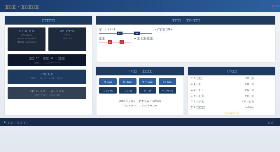
The crane electrical control system uses a distributed control architecture built around three levels: the main control cabinet in the operator cab, the bridge electrical cabinet, and the trolley electrical cabinet. The main control cabinet in the cab houses the PLC master station, the touch screen HMI, and the control grips and pushbuttons for each motion. The bridge electrical cabinet—mounted on the walkway along the main girder—contains the VFDs or speed-control resistors for the two bridge drive motors, braking resistors, terminal blocks, and auxiliary control components. The trolley electrical cabinet, mounted on the trolley platform, houses the VFDs and braking units for the hoisting motor and trolley motor, the load limiter signal transmitter, brake rectifiers, and auxiliary control components. Power and communication between the three cabinets run through trailing cables or conductor rails. The bridge connects to the cab via multi-core cables routed through cable pulleys and a trailing cable system, while the trolley connects through a suspended trailing cable. The system is powered by a three-phase five-wire TN-S supply, with the main power entering the cab's main control cabinet through a main circuit breaker; each motion is individually controlled through its own circuit breaker and contactor.
| Comparison Item | S7-1200 1215C | S7-1500 1511 |
|---|---|---|
| CPUPerformance | Mid-Range | High-End |
| working memory | 150KB | 750KB |
| PROFINETOpening | 2Unit | 2Unit(Includingnetwork switch) |
| PROFIsafe | Not Supported | Supported |
| DI/DOExtension | Maximum8Unit Module | Maximum32Unit Module |
| Application Scenarios | Medium-Dutyoverhead crane≤50t | Heavy-Dutyoverhead crane/Safety PLC |
| Cost Comparison | Benchmark | High60%~80% |
Electrical Schematic Design
The electrical schematic is developed using a layered design approach, divided into four sections: main power circuit, control circuit, PLC I/O wiring, and safety circuit. The main power circuit diagram illustrates the power supply paths for each motor, covering the connections between the main incoming circuit breaker, main contactor, branch circuit breakers for each mechanism, VFD input reactors, frequency inverters (or speed-control contactors), VFD output reactors, and the motor junction boxes, with component model numbers, specifications, and conductor cross-sections clearly labeled. The control circuit diagram details the VFD control terminal wiring, brake contactor coil control circuits, limit switch and proximity switch wiring, and PLC digital input/output connections, with wire numbers and terminal designations marked. The PLC I/O wiring diagram is organized by module type, showing digital input, digital output, analog input, and communication interface connections, with module model, channel numbers, and corresponding wire numbers for sensors and actuators. The safety circuit diagram shows the series loop comprising the emergency stop button chain, door limit switch chain, overload protection contacts, and the emergency stop relay. The safety circuit employs a redundant design using normally-closed contacts in series, and any interruption in this circuit directly cuts power to the main contactor coil.
Key Component Selection
S7-1200 1215C
Siemens G120
KTP700 Basic PN
Resistive Strain Gauge Type
Multi-turn Absolute Type
PLC Program Structure
The PLC program is developed using a structured programming approach. The main routine (OB1) cyclically calls each function block at a 10ms control interval. Key function blocks include: System Initialization (FC_Init) — checks sensor status and performs system self-diagnostics at power-up, enabling startup only when all conditions are normal. Hoist Control (FC_Hoist) — manages hoisting/lowering, acceleration/deceleration, zero-speed holding, brake control, and overload protection logic. This is the most critical block, requiring precise timing coordination between brake control and VFD run commands. Long Travel Control (FC_Trolley) and Trolley Control (FC_Crab) handle bi-directional travel and limit logic for the horizontal mechanisms. Safety Protection (FC_Safety) continuously monitors the integrity of all safety circuits — any interruption immediately halts all mechanisms and logs an alarm. Fault Diagnosis (FC_Diag) collects fault words from each VFD for consolidated display. Data Logging (FC_Log) writes operational data and alarm records to the HMI memory or uploads them to a remote platform via the communication module. Analog Processing (FC_Analog) handles 4~20mA signals from the load limiter sensor and anemometer, performing engineering unit conversion and threshold comparisons.
HMI Interface Design
The HMI touchscreen interface is organized into four main pages by function. The main monitoring page displays the overall operating status of the overhead crane, including travel direction indicators for each mechanism, current lifting capacity (shown both numerically and as a bar chart), lifting height, crane bridge and trolley positions, travel speed, brake status for each mechanism (open/closed indication), and overload warning and alarm indicators. The alarm page lists all alarm records in reverse chronological order, showing the alarm time, alarm description (e.g., "Hoisting mechanism brake fails to open fully"), alarm level (warning/alarm/emergency), and operator acknowledgment status. The parameter settings page features two-level access control: operator-level access allows adjustment of lifting height limits, travel limit parameters, acceleration/deceleration ramp times, and operator preference settings; engineer-level access enables adjustment of lifting capacity calibration coefficients, VFD communication parameters, and various protection thresholds. The historical data page provides trend curves for operational data (lifting capacity, lifting height, travel speed, etc.) along with data export functionality. The HMI communicates with the PLC via PROFINET with a data refresh cycle of 100 ms.
On-Site Commissioning and Verification
On-site commissioning follows a systematic procedure: pre-power inspection (verifying wiring consistency against drawings, measuring insulation resistance of all power circuits at ≥0.5 MΩ, and confirming all circuit breakers are in the open position); power-on testing (energizing in stages—first applying control power to confirm proper PLC and HMI startup, then applying main power to each mechanism motor); no-load testing (inching each mechanism to confirm travel direction matches control input, and adjusting limit switch positions and actuation travel); loaded testing (progressively loading up to rated load, calibrating the load limiter zero and full-scale points, and verifying overload protection operation); and functional verification (systematically testing all safety protection functions including emergency stop, limit switches, overload, door interlock, brake fault, and encoder disconnection protection, with results recorded on the commissioning checklist). Any issues identified during commissioning are logged in the commissioning log and re-verified after corrective action.
