

Crane Anti-Sway Control: Input Shaping, Closed-Loop & AI
Crane Anti-Sway Control Explained: Input Shaping, Closed-Loop Feedback, and AI-Based Solutions Compared
Quick Answer: Four mainstream crane anti-sway control technologies compared—input shaping, closed-loop feedback, adaptive control, and AI-based predictive control—from the physical model to PLC implementation.
Crane anti-sway control refers to the use of control algorithms to suppress the back-and-forth oscillation of a suspended load during travel, enabling fast, precise load positioning. The crane–load system is fundamentally a nonlinear pendulum model—crane acceleration excites the sway angle, which in turn affects the effective driving force. Without anti-sway control, a fully loaded crane running at full speed can experience sway angles of 15–25°, with residual oscillation lasting 15–30 seconds after stopping—severely limiting automated cycle times. This article starts from the physical model and compares four mainstream anti-sway approaches.
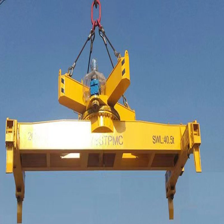
Understanding the Crane Load Swing Physics Model
The overhead crane–load system is simplified as a pendulum model: crane mass M, load mass m, and wire rope length L. After small-angle linearization, the equations of motion are (M+m)·ẍ + m·L·θ̈ = F and L·θ̈ + ẍ + g·θ = 0. The velocity-to-sway-angle transfer function is G(s) = -s/(L·s²+g), and the oscillation period is T = 2π·√(L/g). The table below summarizes sway characteristics for different rope lengths:
| Wire Rope Length | Swing Period | Swing Frequency |
|---|---|---|
| 1m | 2.0s | 0.50Hz |
| 5m | 4.5s | 0.22Hz |
| 10m | 6.3s | 0.16Hz |
| 20m | 9.0s | 0.11Hz |
Longer rope lengths result in longer sway cycles and lower frequencies. At a 10m rope length, the maximum sway angle can reach 25°, directly challenging the positioning accuracy and cycle time of automated overhead cranes.
Comparing Four Anti-Sway Solutions for Overhead Cranes
| Solution | Positioning Accuracy | Additional Cost | Application Scenarios |
|---|---|---|---|
| A: Input Shaping | ±50mm | ¥0(Software-Only) | Semi-automatic/Low Speed |
| B: Closed-Loop Feedback | ±10mm | ¥5,000~15,000 | Recommended, L3Standard |
| C: Adaptive Control | ±5mm | ¥15,000~30,000 | Variable Rope Length/Variable Load |
| D: AIReinforcement Learning | ±3mm | ¥30,000+ | L4Unmanned High-Speed |
Input Shaping for Anti-Sway Control
Input shaping superimposes delayed, inverted pulses onto the travel speed command, causing the oscillations from two successive motions to cancel each other out. The Zero Vibration (ZV) shaper uses coefficients A₁=0.241 and A₂=0.759, with a delay time of T_n/2, requiring only a ring buffer and zero hardware cost. Field tests show that a 10% error in rope length can amplify residual sway by 2 to 3 times, making this approach suitable for semi-automatic applications with travel speeds below 0.5 m/s and an accuracy of ±50 mm.
| Shaper Type | Number of Pulses | Period Error Sensitivity | Response Start Button |
|---|---|---|---|
| ZV | 2 | Sensitive | Fastest |
| ZVD | 3 | Medium | Medium |
| EI | 5 | Insensitive | Slower |
Option B: Closed-Loop Feedback Control (Recommended)
Closed-loop feedback adds an inclination sensor to the lifting spreader and uses a PID controller to compensate the speed command. The compensation logic is: output speed = planned speed – (Kp × sway angle + Kd × angular velocity). When the load swings backward, the overhead crane accelerates forward to dampen the swing; when it swings forward, the crane decelerates. Within 500 mm of the target position, the system switches to fine-tuning mode, adding an integral term to eliminate steady-state deviation. Kelude Heavy Industry has integrated closed-loop anti-sway functionality into its crane safety monitoring system (see the SIL3 Safety Monitoring Solution for details).
Sensor Selection
| Sensor Shaper Type | Model | Accuracy | Price |
|---|---|---|---|
| Inclination Sensor | SICK TMS88 | ±0.1° | ¥3,000 |
| Inclination Sensor(Domestic Alternative) | INX360D | ±0.3° | ¥1,500 |
| 2DLiDAR | SICK LMS111 | ±0.5° | ¥8,000 |
| Vision-Based Sway Measurement | Basler Camera+YOLO | ±0.2° | ¥6,000 |
| MEMS IMU | BMI088 | ±0.5° | ¥200 |
Recommendation: For L3 unmanned overhead crane applications, the SICK TMS88 (¥3,000) delivers ±10mm accuracy; for L4 unmanned overhead cranes, a dual-redundancy approach combining tilt sensors with vision systems is recommended.
Adaptive Control for Variable Lifting Heights
When the lifting height changes dynamically during operation, the sway period shifts accordingly. Adaptive control reads the rope length in real time via the hoisting encoder and dynamically updates PID gains: Kp=0.8/√L, Kd=0.3×√L. For longer ropes, the proportional gain is reduced to prevent overshoot; for shorter ropes, it is increased to quickly dampen sway. Field tests across a rope length range of 3–20m show residual sway angles stabilizing at 0.3–0.8°, compared to 2–5° deviation in non-adaptive mode.
AI Deep Reinforcement Learning (DQN) for Sway Control
Traditional PID control struggles with nonlinear factors such as wind disturbances and offset loads. DQN learns optimal control policies through autonomous trial and error: a 6-dimensional state space [position, velocity, sway angle, angular velocity, rope length, load mass], 5 discrete actions {-2,-1,0,1,2} m/s², and a 128-128 two-layer fully connected network converging after 50,000 training iterations. Under a level-3 wind disturbance (5 m/s crosswind), DQN maintains residual sway angles within ±0.5°, whereas closed-loop PID reaches ±2.3°.
On-Site Tuning and Measured Performance Data
Tuning Procedure: Step 1: Measure the sway period. Step 2: Open-loop testing with input shaping (steady-state sway angle <3°). Step 3: Closed-loop coarse tuning (Kp=1.0, Kd=0.5). Step 4: Fine-tuning (increase Kp if sway is slow, decrease Kp and increase Kd if oscillation occurs, add integral action for bouncing). Step 5: Verification (residual sway angle <2°, positioning time <5s).
| Operating Condition | Maximum Swing Angle | Residual Swing Angle | Settling Time |
|---|---|---|---|
| No-Load Full Speed(3mRope) | 4.1° | 0.8° | 3.5s |
| 50%Full Load Full Speed(5mRope) | 3.5° | 0.6° | 4.2s |
| Rated Load Full Speed(8mRope) | 2.8° | 0.4° | 5.0s |
| Long Rope Full Speed(15mRope) | 1.5° | 0.3° | 6.0s |
After implementing a closed-loop feedback solution across a 32t overhead crane fleet at an automotive plant, average positioning time per cycle dropped from 32s to 22s, boosting production capacity by 31%.
Kelude Anti-Sway System Advantages
Kelude's overhead crane anti-sway control system supports three switchable modes—input shaping, closed-loop feedback, and adaptive control—with PLC programs preloaded on Siemens S7-1200/1500 controllers. The Inclination Sensor comes standard with a SICK TMS88 (±0.1°), with an optional dual-redundancy vision-based sway detection module. Parameters can be remotely adjusted online through the crane digitalization remote monitoring platform (see Crane Digitalization Remote Monitoring Solution), eliminating the need for on-site engineer visits. Kelude also offers complimentary anti-sway performance assessments and on-site commissioning services.
