

Why Grab Buckets Keep Jamming: Angle, Shape & Cycle Issues
A straw grab that keeps jamming is almost always down to three missteps—skipping the repose angle when sizing, using straight tines instead of curved ones, and running the pickup cycle by feel. Any one of these is enough to ruin your day; all three together will have you stopping the line three times a shift.
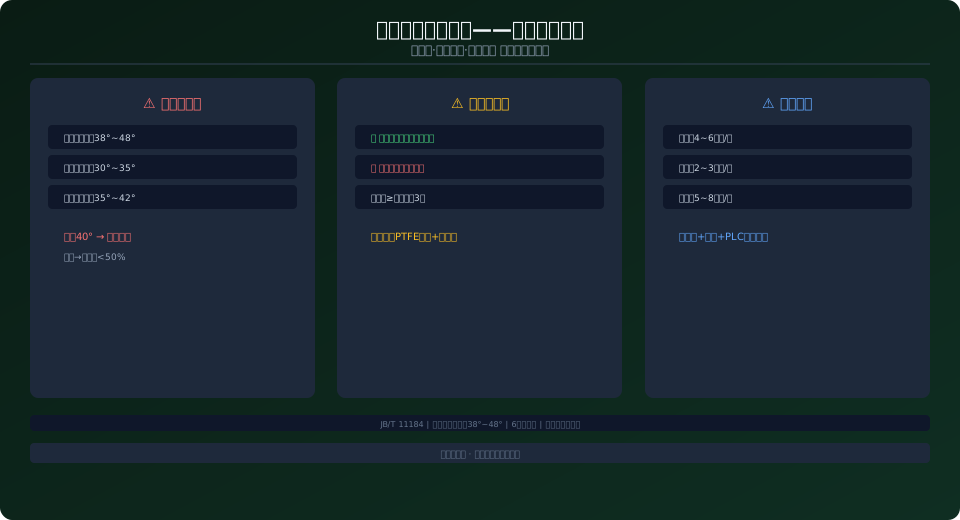
Straw Grab vs. Refuse Grab: What’s the Real Difference?
At a glance they look the same—both hang from an overhead crane and use multiple tines to scoop up material. But straw and refuse behave completely differently under load. Refuse is a mixed bag: heavy and light, wet and dry all thrown together. Straw is fibrous, interlocking, and has a repose angle that can reach a dramatic 38°–48°. That 10°–15° gap is exactly why straw’s “self-locking effect” in a storage hopper is far stronger than ordinary refuse—without external intervention, it will bridge across the hopper opening on its own.
The higher the repose angle, the smaller the “effective flow radius” inside the hopper. In a 4 m diameter round hopper, shredded straw with a 45° repose angle leaves an effective discharge diameter of only about 2.5 m—that’s nearly 30% less opening space for the grab to work with. If you size the grab without accounting for the reduced fill caused by the repose angle, actual pickup efficiency will fall well short of the design value. This is the root cause behind the all-too-common complaint in biomass power plants: “the grab is big enough, but it still can’t keep the boiler fed.”
Why Tine Shape Matters: Straight vs. Curved Tines
Straw is a long-fiber material, typically 20–80 mm in length—just the right size to wedge into the gaps between tines on a conventional grab. Curved tines maintain a continuous radius from tip to root, so straw slides off the arc surface instead of embedding itself. Keep the tine spacing at least three times the average straw length—for 50 mm straw, that means a minimum gap of 150 mm. Add a PTFE coating on the inner surfaces to cut the friction coefficient from 0.4 to below 0.05, and fit a rubber scraper on the back of the grab to clear residual straw automatically. With these three measures in place, wrap-related downtime drops from twice a week to once a month.
Pickup Cycle Timing: Too Fast Clogs, Too Slow Starves
| Bulk Material Type | Recommended Cycle Rate | Angle of Repose | Grapple Tine |
|---|---|---|---|
| Chopped Straw | 4~6min/cycles | 38°~48° | 6Tine Arc+PTFE |
| Rice Husk | 2~3min/cycles | 30°~35° | 8Tine Arc+Serrated Cutting Edge |
| Wood Chips | 5~8min/cycles | 35°~42° | 6Tine Arc+Wear-Resistant Cutting Edge |
A 30MW biomass power plant consumes roughly 18–22 t/h of straw. At 2 t per grab, that translates to 9–11 grab cycles per hour. However, when the level sensor detects that the angle of repose has exceeded a critical threshold, the grab must pause to perform a bridging/arching break action. The PLC, working with the level sensor and VFD, enables "intelligent intermittent grabbing"—something manual operation simply cannot achieve. The special requirements for biomass materials outlined in JB/T 11184 are often overlooked, which is why actual production capacity after commissioning frequently falls to only 60%–70% of the design value.
Testing Methods for Straw Material Properties
The first step in grab selection isn't flipping through a supplier's catalog—it's sending the material to a lab for three specific tests.
Test 1: Bulk Density Test — Samples are tested at different moisture content levels (15%, 30%, 45%, 55%) to establish a density-versus-moisture curve.
Test 2: Angle of Repose Test — Using the standard Φ300mm disc method, each material is measured three times at each moisture level, and the average is taken.
Test 3: Fiber Length Analysis — A sample of 100 straw stalks is measured for length distribution, calculating the mean and standard deviation. These three data sets are the true input parameters for grab design—far more reliable than any empirical formula.
If lab facilities aren't available, on-site quick tests can still yield useful reference data. On-site bulk density: Fill a container of known volume (e.g., a 200L drum) with material, weigh it on a forklift scale, subtract the empty drum weight, and divide by the volume. On-site angle of repose: Pile material about 1m high on flat ground, take a side photo with a phone, and use a protractor app to measure the slope angle directly. On-site fiber length: Randomly select 50 stalks, measure each with a tape measure, and calculate the mean and standard deviation in Excel. While less precise than lab data, these measurements are infinitely better than "estimating from experience." Field experience shows that angle of repose estimates based on gut feeling typically carry an error of 10°–15°—which is exactly why so many grabs turn out to be the "wrong size" once they arrive on site.
Integrated Feed System Design for Biomass Power Plants
The grab isn't a standalone piece of equipment—it's the first link in the material handling chain: grabbing → conveying → crushing → feeding → combustion. If the feed rate at the first link doesn't match the combustion rate at the last, the entire system will oscillate between "waiting for material" and "overflowing." Integrated feed system design requires defining three core parameters:
- ① Hopper Storage Capacity — Must provide at least 4–6 hours of buffer for full boiler load. Anything less risks fuel starvation the moment the grab stops.
- ② Feeder Rate — The maximum output of the screw or chain feeder should be 120%–150% of the boiler's full-load requirement, leaving adequate adjustment margin.
- ③ Interlock Control Logic — When the hopper level drops below the low setpoint, the PLC automatically increases the grab's grabbing frequency. When the level exceeds the high setpoint, the grab frequency is reduced or paused to prevent overflow.
A typical 30MW biomass plant feed system configuration: straw consumption of 18–22 t/h, hopper capacity of 100–130 t (approximately 5–6 hours of buffer), grab capacity of 2–2.5 t per cycle, and a grabbing cycle time of 5–6 minutes. During normal operation, the grab cycles 10–12 times per hour, achieving a utilization rate of about 85%–90%. When boiler load fluctuates (e.g., dropping from 100% to 70%), the PLC automatically reduces the grabbing frequency from 12 to 8 cycles per hour within just 3 cycles—a response speed that's impossible with manual operation. This underscores why biomass plant grab cranes must be equipped with a PLC Control System rather than relying solely on a simple VFD and joystick.
Case Study: Retrofitting a 15t Straw Grab
A 30MW biomass power plant, commissioned in 2019, initially used a 15t direct-type hydraulic grab with a design capacity of 25 t/h. By the third month of operation, severe issues emerged: straw entanglement caused 2–3 shutdowns per shift for cleaning, each lasting 30–40 minutes, reducing actual capacity to just 12–15 t/h—only 50%–60% of the design value. The boiler was forced to operate at reduced load, resulting in approximately 15% power generation loss.
In 2020, a retrofit was carried out: the straight-type shells were replaced with curved shells (changing from 6 to 8 shells), the inner surface of the shells was coated with PTFE (0.3mm thickness), the gap between shells was increased from 120mm to 180mm (to accommodate the average straw length of 55mm), rubber scraper plates were added to the back of the grab, and the hydraulic system was upgraded to proportional control (enabling three-stage open/close force control). The total retrofit cost was approximately ¥350,000 (including ¥150,000 for shell replacement, ¥120,000 for hydraulic upgrade, and ¥80,000 for PLC programming). After the retrofit, the grabbing capacity recovered to 22–24 t/h (88%–96% of the design value), entanglement-related shutdowns dropped from 2–3 per shift to just 1–2 per week, and the boiler returned to full-load operation. The ¥350,000 investment was recouped within 4 months through increased power generation, subsequently generating an additional ~¥1 million in annual revenue. This case illustrates a fundamental principle: grab design isn't about plugging numbers into a parameter table—it's about understanding the material's mechanical behavior and customizing the solution accordingly.
Frequently Asked Questions
Q: What standard should be used for straw grab selection?
A: The core standards are JB/T 11184 and GB/T 10603. During selection, pay special attention to: ① Measured angle of repose (don't rely on tables); ② Moisture content fluctuation range (affects density verification); ③ Fiber length distribution (determines shell gap). The owner must complete material property testing before tendering.
Q: How do you measure the angle of repose?
A: Laboratory method: Take a 2–3 kg sample of straw and pile it naturally on a Φ300mm disc. The angle of repose = arctan(height / radius). On-site quick test: Pile material, take a side photo, and measure the slope angle with a phone protractor app. Test at different moisture levels—as moisture increases from 15% to 55%, the angle of repose can rise from 38° to over 50°.
Q: What is the lifespan of a straw grab?
A: With a M5 work duty classification, the design life is 15–20 years, influenced by silicon content—the shell cutting edges wear 1–2mm per year. Curved shells last 30%–50% longer than straight-type shells. Key wear parts: cutting edges need replacement every 2–4 years, seals every 1–2 years, and PTFE coating reapplication every 1–2 years.
Q: Can one grab handle both straw and wood chips?
A: If the mix is 80% straw and 20% wood chips, the grab can be designed based on straw parameters. If wood chips exceed 40%, the shell gap needs to be increased, which will reduce pure straw grabbing efficiency. Best practice: when feeding two materials in separate time slots, design for the more challenging material.
For custom biomass power plant grabs, consult the Kelude technical team—test your material first, then we'll design the solution.
