

Bridge Crane Conductor Rail Poor Contact: Fixes
Core Issue: Poor contact in overhead crane conductor rails primarily manifests as abnormal sparking at the current collector (spark grade should not exceed 1¼ under normal operation), supply voltage fluctuations beyond ±10% of rated value, and abnormal noise or vibration from the motor during operation. Field statistics show that poor contact accounts for over 60% of conductor rail power supply system failures, with excessive carbon brush wear (remaining length <5mm) and increased oxidation layer on the rail surface being the two leading causes.
The conductor rail system serves as the power supply artery for both the crane bridge and trolley travel. When the contact resistance between the collector carbon brush and the rail rises from a normal tens of milliohms to hundreds of milliohms or even several ohms, the entire power circuit begins to malfunction—the VFD trips frequently, the motor delivers insufficient torque, and localized overheating occurs along the rail. The following sections provide a systematic solution covering typical symptoms, root cause analysis, troubleshooting procedures, and maintenance practices.
Common Symptoms of Conductor Rail Contact Failure
The diagram below outlines the complete troubleshooting workflow from fault detection to root cause identification:
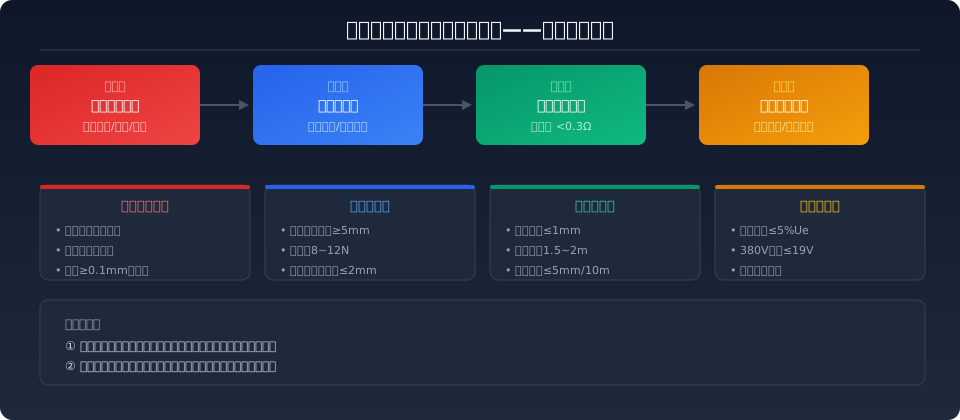
1. Abnormal sparking at the collector-rail contact point—Under normal conditions, the spark grade between the collector carbon brush and the rail should remain within 1¼ (i.e., faint micro-sparks). When contact resistance increases, sparking intensifies noticeably to Grade 2 or even Grade 3 (continuous jet-like discharge), accompanied by a crackling sound that is particularly noticeable during nighttime inspections.
2. Supply voltage fluctuation during crane operation—Measuring at the collector output with a multimeter, the voltage fluctuation under normal operation should stay within ±5% of the rated voltage. With poor contact, voltage can momentarily drop by 10%–30%, causing the VFD to repeatedly report undervoltage faults and the crane bridge or trolley to exhibit a jerky, stop-and-go motion.
3. Localized overheating of the rail—The contact resistance at a poor-contact point is far higher than that of a healthy section, generating Joule heat when high current passes through. Using an infrared thermometer, the temperature rise at the fault point can be 15–30°C higher than that of a normal section, and in severe cases may exceed 60°C. A thermal imaging camera allows rapid scanning to pinpoint the fault location during nighttime operations.
Three Root Causes of Poor Contact
Rail-side: surface oxidation and carbon buildup—Copper or aluminum rails exposed to the workshop environment over time develop a surface film of copper oxide (CuO) or aluminum oxide (Al₂O₃). These oxide layers have extremely poor conductivity and can raise contact resistance from a normal tens of milliohms to hundreds of milliohms or even several ohms. In foundries, stamping shops, and other facilities with oil mist or dust in the air, the rail surface also accumulates grease and carbon particles, further degrading electrical performance.
Collector-side: carbon brush wear and spring fatigue—The carbon brush is a wear part; the standard requires a remaining length of no less than 5mm (new brushes typically measure 20–30mm). Below this limit, the contact area shrinks sharply, current density increases, and sparking and heating intensify. The compression spring inside the collector loses its resilience after extended service—the standard contact pressure should be 8–12N; below 6N the contact becomes unreliable, while above 15N it accelerates carbon brush wear.
Installation environment: alignment deviation and structural loosening—Loose rail brackets, rail deformation, and workshop vibration can cause the shaft alignment deviation between the collector and the rail to exceed the allowable tolerance (generally ≤2mm), resulting in uneven brush wear and intermittent contact. Rail joints are the most vulnerable points—loose bolts or oxidized joints are common starting points for voltage fluctuations.
Four-Step Troubleshooting Procedure
Step 1: Visually inspect the rail surface condition—With the power disconnected, examine the entire rail length for uniform surface color, visible oxidation patches, or arc burn marks. Pay particular attention to rail joints, which are the most prone to loosening and oxidation. A healthy rail surface should show uniform metallic luster; darkening or rainbow-colored patterns indicate oxidation.
Step 2: Inspect the collector carbon brush—Measure the remaining brush length (≥5mm), check the clearance between the brush and the brush holder (0.1–0.3mm), and use a spring scale to verify contact pressure (8–12N). The brush should slide freely within the holder without noticeable play. Uneven wear exceeding one-third of the brush cross-section requires replacement.
Step 3: Measure contact resistance and voltage drop—With the crane operating at full load, use a milliohm meter to measure the resistance between the collector output terminal and the rail input terminal; the normal value should be below 0.3Ω. Simultaneously measure the full-load voltage drop: in a 380V power supply system, the voltage drop from the rail power supply inlet to the collector output should not exceed 19V (i.e., 5% of rated voltage). An abnormal increase in voltage drop along any section indicates a poor-contact point in that segment.
Step 4: Check rail fixing and shaft alignment—Verify that the spacing between rail brackets is uniform (standard spacing 1.5–2m), joint gaps are ≤1mm, and the vertical deviation between the collector arm and the rail is ≤2mm. Use a laser alignment tool or plumb line for measurement assistance; correct any out-of-tolerance deviation by adjusting the bracket bolts.
Fault & Solution Reference Table
| Fault Symptom | Possible Cause | Solution | Preventive Interval |
|---|---|---|---|
| Current Collector Increased Sparking | Carbon brush Wear/Spring Insufficient Pressure | Replace Carbon brushto Remaining≥5mm, Air Compressor Spring Force to8~12N | Quarterly Inspection |
| During Operation Voltage High Fluctuation | Conductor Rail Joint Loosening/Oxidation | Tightening Joint Bolt, Sand off oxide layer with fine emery cloth and apply conductive grease | Every Half Annual Inspection Quarterly Inspection |
| Severe Local Overheating of Conductor Rail | Contact of This Section Resistance Excessive | Troubleshoot This Section Jointand Current Collector, Replace conductor rail section if necessary | Monthly Infrared (Thermography)Inspection |
| Carbon brush Severe Uneven Wear | Collector Armshaft alignment Deviation>2mm | Re-Calibration Current Collector Mounting Position, Ensureshaft alignment Deviation≤2mm | After Installation and Every Six Months |
| Frequent Undervoltage Alarm Voltage Fault | power supply line Excessive Line Voltage Drop | Increase Supply Conductor Size Cable Cross-Section, Shorten Power Feed Point Spacing to≤50m | Determined at Design Stage |
| Pitting or Arc Erosion on Conductor Rail Surface | Caused by Prolonged Spark Discharge | Minor: Repairable by Grinding/Polishing, Severe: Conductor Rail Section Replacement Required | Each Time Inspection Visual Inspection |
Preventive Tiered Maintenance Program
To fundamentally reduce conductor rail contact failures, establishing a tiered maintenance system is essential:
Daily Inspection (Per Shift) — Before operation, the operator checks the current collector for abnormal sparking or noise and records findings in the shift handover log. Visually inspect the rail surface for noticeable discoloration or dust accumulation.
Monthly Inspection — Four checks are mandatory: measure remaining carbon brush length (≥5 mm), test spring pressure (8–12 N), visually inspect the rail surface condition, and perform infrared thermography scanning (temperature deviation between sections ≤10°C).
Quarterly Maintenance — Thoroughly clean dust and grease from the rail surface, wipe oxidized sections with anhydrous alcohol, and reapply conductive grease (0.1–0.2 mm thickness). Verify tightening torque on all joint bolts and measure insulation resistance of each rail section to ground (≥1 MΩ).
Semi-Annual Calibration — Measure shaft alignment deviation between the collector arm and conductor rail (≤2 mm), check support bracket spacing (1.5–2 m) and joint gaps (≤1 mm), and correct immediately if out of tolerance.
Regarding technical requirements, the design and installation of conductor rails must comply with the power supply system provisions of ISO 4301 Crane Design Standard — this standard requires that the conductor rail power supply system maintain a voltage drop at the end of the power supply of no more than 5% of rated voltage under maximum working current. Additionally, routine inspection and maintenance of the equipment must meet the requirements of ISO 12480 Safety Code for Lifting Appliances, which explicitly states that conductor rails and current collectors must be kept clean, and carbon brushes must be replaced promptly when worn to the limit position to ensure supply reliability and operator safety. For overall system selection and configuration of the conductor rail system, further reference can be made to the systematic analysis in Arc Detection and Online Power Supply Safety Monitoring & Early Warning Solutions for Overhead Crane Conductor Rail Current Collectors.
Safety Notice: All inspection and maintenance work on conductor rails and current collectors must be performed only after the crane is de-energized and a "Do Not Close" warning tag is posted. The conductor rail carries 380V AC — contact while energized can cause severe electric shock. Maintenance personnel must wear insulating gloves and insulating shoes and use insulated tools. After maintenance is complete, use a Megohmmeter (Insulation Tester) to measure the insulation resistance of each phase to ground, and only resume power and test operation after confirming readings are ≥1 MΩ.
Common Questions & Troubleshooting
Q: Why does the VFD frequently trip on undervoltage when the crane rail has poor contact?
A: The DC bus voltage detection circuit inside the VFD is highly sensitive to input voltage fluctuations. When poor rail contact causes a transient voltage drop exceeding 15% (i.e., below 323V), the VFD's undervoltage (UV) protection triggers within tens of milliseconds, causing a protective shutdown. Per ISO 4301 requirements, the power supply system must maintain a voltage drop of no more than 5% under maximum working current — regularly measuring the voltage at the supply end is key to preventing this type of fault.
Q: At what wear level must the current collector carbon brush be replaced? How should new brushes be selected?
A: The carbon brush must be replaced immediately when the remaining length is less than 5 mm (approximately 25% of the original length). When selecting replacements, ensure the brush material matches the rail material — copper rails require metal-graphite brushes with 60%–80% copper content, while aluminum rails require brushes with 40%–60% copper content to prevent electrochemical corrosion. The brush cross-section must fit the brush holder with a clearance of 0.1–0.3 mm — too tight causes binding, while too loose results in wobble and uneven wear.
Q: After sanding off the oxide layer on the rail surface, how soon does it need to be treated again?
A: Conductive grease (0.1–0.2 mm thickness) should be applied immediately after sanding to prevent re-oxidation. In a standard workshop environment, re-inspection is needed in approximately 6–12 months. In workshops with high temperature, high humidity, or corrosive gases (e.g., electroplating or pickling facilities), inspection every 3–6 months is recommended. If the rail oxidizes abnormally fast, consider upgrading to stainless steel copper-clad rail or adding a protective cover to reduce environmental exposure.
Q: How can I quickly pinpoint the exact fault location of poor rail contact?
A: The most effective method is the segmented voltage drop test — with the crane running at full load, measure the voltage to ground every 5–10 m along the rail starting from the supply end, and plot a voltage-versus-position curve. A sudden voltage drop exceeding 3V indicates the poor contact point. Alternatively, use an infrared thermal imaging camera for rapid scanning — the faulty contact point will run at least 5–10°C hotter than normal sections. For workshops that do not operate at night, running the crane in darkness and visually locating the densest sparking area is also a quick way to identify the fault point.
