

Overhead Crane Safety Brake vs Service Brake: TSG 51 Requirements
The safety brake (emergency brake) on a crane is responsible for crash-back braking to prevent load free-fall, with a safety factor of M7~M8 ≥ 2.0. The service brake handles normal hoisting, lowering, and deceleration stops. The hoisting mechanism must be equipped with at least 2 brake sets, of which at least 1 must be an independent safety brake. The two brake systems must be fully independent in their control circuits, sharing no electrical paths whatsoever.
Kelude Heavy Industry strictly adheres to the double-brake configuration standard in the design and manufacturing of overhead cranes. In the hoisting mechanism, the brake is the last line of defense against load drop. Many buyers and inspectors confuse the functional boundaries between safety brakes and service brakes during selection and acceptance — one is designed for emergency load retention, the other for routine deceleration and stopping. They differ fundamentally in safety factor, control circuitry, and acceptance criteria. This article, based on GB/T 3811 Crane Design Standard and TSG 51 Safety Technical Specification for Special Equipment, systematically breaks down the core differences and the configuration and acceptance requirements for both brake types.
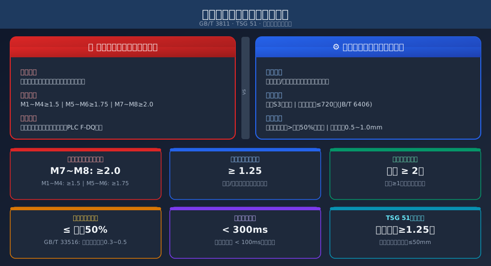
Safety Brake vs. Service Brake: Definitions and Key Differences
Safety Brake — also referred to as the emergency brake or auxiliary brake, serves a single purpose: to apply braking in emergency situations (e.g., overspeed, power loss, or service brake failure). It acts directly on the drum or high-speed shaft to prevent the load from free-falling. The safety brake must have its own dedicated control circuit, driven directly by the F-DQ module of a safety PLC, and must never share contactors or relays with the service brake.
Service Brake — also known as the operational or running brake, handles deceleration and stopping of the hoisting mechanism during normal operations (hoisting, lowering, and holding). It is typically mounted between the electric motor and the gearbox, controlled by a VFD or contactor, and is rated for up to 720 start-stop cycles per hour under S3 duty classification.
The core differences between the two lie in four dimensions: safety factor, mounting position, control method, and acceptance standard. The comparison table below lists the key technical parameters for the hoisting mechanism:
| Comparison Parameter | Safety Brake | service brake |
|---|---|---|
| Function Positioning | Emergency Brake application, Anti-fall Protection, Triggered Only in Abnormal Conditions | Normal Hoisting and Lowering Deceleration, Stopping, Frequent Duty |
| Safety factor(Hoisting / Lifting) | M1~M4≥1.5, M5~M6≥1.75, M7~M8≥2.0 | M1~M4≥1.5, M5~M6≥1.75, M7~M8≥2.0(Same as Standard) |
| Mounting Position | Drum End or High-Speed Shaft End, Independent Mounting | Electric Motor With Reducer / Gearbox Between |
| Control Circuit | Independent F-DQSafety Output, Withservice brake Electrical Isolation | Frequency Inverter / VFDDOEnd or Contactor Control |
| Response time | ≤100ms(Recommended), Qualified≤300ms | ≤300ms(Normal Operating Conditions) |
| Duty Classification | Rarely Actuated(Only Testingand Emergency Triggering) | S3Intermittent Duty Cycle, Per Hour≤720Cycles |
Regulatory Standards and Configuration Requirements
The configuration requirements for safety brakes are defined by two core regulations: GB/T 18443 "Crane Brakes" specifies brake selection and technical requirements, mandating that hoisting mechanisms must be equipped with a double-brake system, with one of the two serving as a safety brake. TSG Q0002 "Safety Technical Supervision Regulation for Lifting Appliances" classifies the double-brake configuration as a mandatory inspection item — a hoisting mechanism without an independent safety brake is directly deemed non-compliant.
Per the GB/T 3811 Crane Design Standard, the safety factor for safety brakes is calculated based on the static torque generated by the rated lifting load. Brake type selection is determined by the mechanism's work duty classification:
M1~M4 (Light Duty) — Safety factor ≥1.5 for hoisting mechanisms. Electromagnetic disc brakes or electro-hydraulic block brakes are acceptable. The safety brake may be the same model as the service brake, but must be mounted on a different shaft end with physically isolated control circuits.
M5~M6 (Medium Duty) — Safety factor ≥1.75. Hydraulic thruster shoe brakes or disc brakes are recommended. Friction linings must be made of high-temperature-resistant materials (operating range -20°C to 150°C). Recommended brake disc materials are QT500-7 or ZG310-570.
M7~M8 (Heavy / Extra-Heavy Duty) — Safety factor ≥2.0. Hydraulic disc brakes are mandatory for the safety brake, with redundant dual brake circuits. The service brake may be a hydraulic block brake of the same specification, but the safety brake's disc diameter must be one size larger than the service brake's to ensure independent braking capability.
For travel mechanisms (bridge and trolley), the required safety factor is lower at ≥1.25, and a service brake alone is typically sufficient. However, for outdoor gantry cranes, the crane travel mechanism should incorporate a wind-resistant brake (rail clamp or anchor device) as an additional safety measure.
Acceptance Inspection and Testing Requirements
Every crane manufactured by Kelude undergoes item-by-item inspection in accordance with TSG 51 before leaving the factory. TSG 51 specifies the following key acceptance tests for double-brake systems — failure of any single item results in a non-compliant determination:
- No-Load Brake Test — With the hoisting mechanism unloaded and lowering at full speed, trigger the safety brake. The stopping distance must be ≤50 mm. The test is repeated 3 times, and the maximum value is used for evaluation.
- Rated Load Brake Test — At 1.0 times the rated lifting capacity, hoist the load to 200 mm above the ground, then trigger the safety brake. The stopping distance must be ≤50 mm with a brake response time ≤300 ms (≤100 ms recommended).
- 1.1× Dynamic Load Brake Test — Apply 1.1 times the rated load and complete a full hoisting and lowering cycle for ≥15 minutes before triggering the safety brake. This test verifies the brake's torque retention capability under hot conditions; the stopping distance must still be ≤50 mm.
- Control Circuit Independence Check — Disconnect all power and control signals to the service brake and confirm the safety brake can still operate independently. Conversely, disconnect the safety brake's control circuit and confirm the service brake is unaffected. Contactors, relays, and terminal blocks for the two brakes must be completely separate.
- Friction Lining Wear Detection — Per GB/T 33516 "Brake Discs and Brake Linings for Cranes," the friction coefficient of the brake lining must remain between 0.3 and 0.5. Mandatory replacement is required when wear exceeds 50% of the original thickness. Standard brake clearance is 0.5–0.8 mm, with a maximum allowable limit of 1.0 mm.
Upon completion of all tests, the inspection body issues a dedicated brake inspection report documenting the measured braking torque, stopping distance, and safety factor verification for each brake. This report is retained in the equipment file.
Routine Maintenance and Common Fault Troubleshooting
Maintenance strategies for safety brakes and service brakes differ significantly — Kelude recommends the following schedules. Since the safety brake operates infrequently, the maintenance focus is on "availability verification" — perform a manual trigger test weekly to ensure the mechanism moves freely, and conduct a monthly load test (light load is sufficient) to track stopping distance trends. The service brake, with its high-frequency operation, requires a "wear management" approach — establish a friction lining wear rate curve to predict replacement windows.
Abnormal Noise from Safety Brake — A sharp squeal during braking is typically caused by oxidation or oil contamination on the brake disc surface. Sand the disc surface with 400-grit sandpaper, wipe clean with anhydrous alcohol, and retest. Noise ≤85 dB(A) is considered acceptable.
Excessive Stopping Distance on Service Brake — When the no-load stopping distance exceeds 50 mm, first check whether the brake clearance exceeds the limit (>1.0 mm), then verify whether friction lining wear exceeds the 50% threshold. If both are normal, check whether the hydraulic thruster's push force has degraded (80% of rated thrust is the lower limit).
Safety Brake Fails to Release — This is usually caused by a burned-out electromagnetic coil or a stuck control relay contact. Measure coil resistance with a multimeter; replace if deviation exceeds ±10%. Measure relay contact resistance; replace the relay if it exceeds 100 mΩ.
Further reading: Three Costly Consequences of Pneumatic Brake Failure on Cranes: Half-Second Air Pressure Lag, Reversed Fail-Safe Logic, and Missing Fire-Resistant Diaphragms in High-Temperature Workshops — A comparison of failure modes and prevention strategies across different brake types.
Frequently Asked Questions
Q: How does GB/T 3811 classify safety factors for hoisting mechanism safety brakes?
A: The standard specifies safety factors for hoisting mechanism brakes based on work duty classification: M1~M4 ≥1.5, M5~M6 ≥1.75, and M7~M8 ≥2.0. The safety brake and service brake share the same safety factor requirements, but the safety brake must be independently mounted with physically isolated control circuits. For travel mechanism brakes, the safety factor is uniformly set at ≥1.25.
Q: What are the inspection items and acceptance criteria for double brakes under TSG 51?
A: TSG 51 requires four item-by-item inspections: no-load braking stopping distance ≤50 mm, rated load braking stopping distance ≤50 mm with response time ≤300 ms, 1.1× dynamic load hot-state stopping distance ≤50 mm, and control circuit independence (complete electrical isolation between the two brakes). Failure of any single item results in a non-compliant determination and the crane is prohibited from service. A dedicated brake inspection report must be issued and archived after testing.
Q: At what wear level must service brake friction linings be replaced?
A: Per GB/T 33516, mandatory replacement is required when brake lining wear exceeds 50% of the original thickness, and the friction coefficient must remain within the 0.3–0.5 range. Normal brake clearance is 0.5–0.8 mm, with a maximum limit of 1.0 mm. The brake disc should also be replaced if grooves deeper than 0.5 mm or cracks appear on its surface. Under S3 duty classification, the typical replacement interval is 6 to 12 months.
Q: What special configuration requirements apply to safety brakes on metallurgical cranes?
A: Overhead cranes for metallurgic plants (A7~A8 duty classification) must meet a safety factor of ≥2.0, plus the following: friction lining temperature resistance rated Class H (180°C), a heat shield fitted over the brake disc with temperature monitoring (alarm threshold 120°C), and a safety brake disc one specification grade larger in diameter than the service brake disc. Both brakes must be wired into a safety PLC with condition monitoring via PROFIsafe communication.
All bridge cranes manufactured by Kelude come standard with a dual-brake system, fully compliant with ISO 4301 and TSG 51 Safety Technical Specification for Special Equipment. For brake configuration parameters and selection guidance on specific models, refer to the ISO 4301 interpretation of crane brake standards or review the technical requirements in IEC 60204-32 for crane braking systems.
