Gantry Crane Selection Guide: MG & MH Type Specs & Design Standards

Gantry Crane Selection: A Complete Knowledge Base. Selecting the right gantry crane involves five core considerations: model parameters (MH/MG/MHL/MHE/MHZ types), main girder design (box girder vs. truss girder), outrigger configuration (L-type, C-type, A-type), travel mechanism power supply, and safety standard compliance. This guide consolidates 21 technical articles on gantry cranes, covering everything from model comparison and structural design to safety configuration and installation acceptance, with reference to ISO 4301 and related international standards—helping you make an informed, cost-effective choice.

Gantry Crane Anatomy: Key Components & Configurations

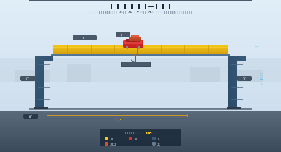
A gantry crane (also known as a gantry or portal crane) is a lifting machine that supports its main girder on a gantry frame, moving along ground-level rails on wheeled carriages. The crane consists of four primary components: the main girder, outriggers (legs), the bridge travel mechanism, and the hoisting mechanism. The main girder spans between the two outriggers, which ride on crane rails via travel bogies. The hoisting mechanism—either an electric hoist or a trolley-mounted unit—traverses along the main girder, enabling three-dimensional material handling. Gantry cranes are classified by main girder design (single or twin), outrigger configuration (L-type, C-type, A-type, or offset), and application (general-purpose, grab bucket, explosion-proof, or container handling).

Gantry crane structural diagram

Gantry Crane Models & Key Parameters

MH Type — Electric hoist gantry crane. Lifting capacity: 1–20 t; span: up to 35 m. Uses an electric hoist as the hoisting mechanism. Simple structure, low dead weight, and economical cost make it ideal for light-to-medium intermittent duty applications.

MG Type — Trolley-type gantry crane. Lifting capacity: 5–50 t; span: 18–50 m. Features a trolley-mounted hoisting mechanism for greater lifting heights and higher work duty classifications. Suited for medium-to-heavy, high-frequency operations.

MHL Type — Offset-leg gantry crane. Lifting capacity: 1–20 t; span: up to 35 m. The main girder is offset to one side of the outriggers, creating a wider lateral clearance for handling long materials such as steel sections, pipes, and timber.

MHE Type — Semi-gantry crane. Lifting capacity: 1–16 t; span: up to 30 m. One outrigger runs on a floor-level rail while the other is suspended from a corbel mounted on the factory building columns. Ideal for facilities with space constraints on one side.

MHZ Type — Grab bucket gantry crane. Lifting capacity: 5–20 t; span: up to 35 m. Equipped with an electric hoist and grab bucket for bulk material handling and grab-type operations.

MHhs Type — Hand chain hoist gantry crane. Lifting capacity: 0.5–10 t; span: up to 20 m. Uses a hand chain hoist instead of an electric hoist, making it suitable for locations without power supply or in explosion-proof environments.

Model Hoisting mechanism Lifting Capacity(t) Span(m) Application Scenarios
MH Type Electric Hoist 1~20 ≤35 medium-light duty, intermittent duty
MG Type Trolleytype 5~50 18~50 medium-heavy duty, high-frequency duty
MHL type Electric Hoist 1~20 ≤35 off-center suspended long-load passage
MHE type Electric Hoist 1~16 ≤30 Factory buildingsemi-portal (side-mounted)
MHZ type Electric Hoist+Grab (grab bucket) 5~20 ≤35 bulk cargo handling, grabbing
MHhs type Hand chain hoist 0.5~10 ≤20 none Power Supply/Explosion-prooflocation

Main Girder Structural Types

The main girder is the primary load-bearing structure of a gantry crane, and its design directly affects the crane's dead weight, stiffness, and manufacturing cost. The two most common girder configurations are the box girder and the truss girder. A box girder is fabricated by welding top and bottom flange plates to two side web plates, forming a closed section that offers high torsional and bending stiffness. This mature, well-established design suits gantry cranes of virtually any capacity or span and is the most widely used girder type in the industry. Truss girders, by contrast, are built from angle steel or steel tubing welded into a spatial lattice structure. They are lighter, offer less wind resistance, and use less steel, making them particularly well suited for outdoor gantry cranes with large spans (exceeding 35 m) or in regions with strong winds. The trade-off is a more complex fabrication process and stringent weld quality requirements at the nodes.

In recent years, hybrid designs such as composite girders and U-girders have also gained traction in the field. A composite girder pairs a box-section main girder with a truss-style lateral bracing system, striking a balance between stiffness and cost efficiency. The U-girder features an open, U-shaped cross-section that simplifies access for internal inspection and maintenance. When selecting a girder type, factors such as rated lifting capacity, span, work duty, operating environment, and manufacturing cost must all be weighed. For a detailed comparison, see Gantry Crane Main Girder Design Comparison.

Outrigger / Leg Structure Design

The outriggers (legs) connect the main girder to the ground-level travel mechanism and play a critical role in determining the crane's overall stability and its operational footprint. Geometrically, outriggers fall into three main types: L-type, C-type, and A-type. L-type legs feature a simple, cost-effective design that is easy to manufacture, making them the standard choice for small- and medium-capacity gantry cranes. C-type legs incorporate an overhang that tucks the lower portion of the leg inward, creating greater clearance for traffic passing between the legs—ideal for facilities where forklifts or other vehicles must drive through. A-type legs use a triangular bracing configuration that provides excellent resistance to lateral forces, making them the preferred option for large-span, heavy-capacity cranes or those operating in high-wind areas.

The connection between the outriggers and the main girder is another key design decision, with two primary options: rigid connection and hinged (pinned) connection. A rigid connection is structurally straightforward but subjects the legs to significant bending moments. A hinged connection, on the other hand, relieves the bending moment transfer between the leg and the girder, improving the stress distribution in the legs—a distinct advantage for large-span cranes. Outrigger selection must be coordinated with the main girder design, span, wheel load, and crane rail foundation. For a deeper dive into leg design parameters, refer to Gantry Crane Outrigger Selection and Design Parameters.

Travel Mechanisms and Power Supply Options

A gantry crane's travel mechanisms consist of the crane travel mechanism (long travel) and the trolley travel mechanism (cross travel). The crane travel mechanism—comprising the drive motor, reducer/gearbox, brake, wheel blocks, and crane rail—moves the entire crane longitudinally along the ground rails. The trolley travel mechanism, mounted on the main girder, moves the load transversely along the girder. Travel drives are configured in one of two ways: centralized drive or individual drive. Centralized drive uses a single motor to power both sides of the crane via a drive shaft, and is typically used on smaller cranes with a span of ≤ 30 m. Individual drive uses separate motors (one or more per side) operating independently, with synchronization ensured by the electrical control system—this is the standard approach for large-span cranes.

Power is supplied to the crane through one of three primary methods: conductor rail (busbar), cable reel, or drag chain. Conductor rail systems are well suited to indoor or outdoor installations with fixed rails, offering reliable power delivery and easy maintenance. Cable reel systems are ideal for large-span cranes or those with long-travel distances, as the reel automatically pays out and retracts the cable. Drag chain systems are commonly used for trolley power supply or short-distance crane travel, providing flexibility and a compact layout. The choice of power supply method depends on the operating environment (indoor vs. outdoor, explosion-proof vs. standard), travel distance, and budget.

Safety Devices and Applicable Standards

As special equipment, gantry cranes must be fitted with a full complement of safety devices in accordance with national standards. These include overload limiters, anti-collision devices, travel limit switches, anti-wind anti-slip devices (rail clamps, anchor devices, rail wedges), anemometers, anti-derailment devices, buffers, emergency stop switches, and audible & visual alarms. The overload limiter is a mandatory component: when the lifting load reaches 105% of the rated lifting capacity, it automatically cuts power to the hoisting mechanism and triggers an audible and visual alarm. Outdoor gantry cranes must also be equipped with an anemometer and anti-wind anti-slip devices to prevent wind-induced sliding under non-operating (working-state wind load) conditions.

The design, manufacture, installation, and inspection of gantry cranes are governed by a comprehensive set of national standards and industry regulations. Key standards include ISO 4301 (Crane Design Standard), GB/T 14406-2011 (General-Purpose Gantry Crane), GB/T 28264-2017 (Safety Monitoring and Management System for Lifting Appliances), TSG Q5001-2009 (Management Rules for the Use of Lifting Appliances), and GB 6067.1-2010 (Safety Regulations for Lifting Appliances). For a detailed breakdown of safety device requirements, see Gantry Crane Safety Device Configuration Guide.

Overload Limiter

Automatically cuts hoisting power and triggers an audible & visual alarm when the load reaches ≥ 105% of rated lifting capacity. Mandatory on all cranes.

Anti-Wind Anti-Slip Devices Rail clamps, anchor devices, and rail wedges. Required on all outdoor gantry cranes to prevent sliding under non-working-state wind loads. anchor devices, and rail wedges. Required on all outdoor gantry cranes to prevent sliding under non-working-state wind loads.

Anemometer

Continuously monitors wind speed and provides early warning with automatic wind-braking activation when the set threshold is exceeded. Required on outdoor cranes.

Travel Limit Switches

Hoisting height limiters and travel limit switches for the crane bridge and trolley prevent over-travel and block lifting collisions.

Gantry Crane Selection & Installation Guide

The gantry crane selection process starts with defining your duty requirements: lifting capacity (including spreader weight), span (rail gauge), lifting height, work duty (A3~A8), and operating environment (indoor/outdoor, temperature range, explosion-proof requirements). Choose the hoisting mechanism based on capacity and duty—an electric hoist type (MH Type) suits light loads and low frequency, while a trolley type (MG Type) is better for heavy loads and high frequency. Select the outrigger configuration based on site space and material handling needs—L-type for general use, C-type for forklift access, and A-type for large spans and wind resistance.

Key quality control points during installation include: the crane rail foundation concrete must reach 100% of its design strength before installation; rail straightness deviation must not exceed 5mm over the full length, with rail gauge deviation within ±3mm; main girder camber should be maintained at L/1000 ±10%; outrigger perpendicularity deviation must not exceed H/1000; and the electrical system must have an insulation resistance of at least 1MΩ and a grounding resistance no greater than 4Ω. After installation, a no-load test run (≥30 minutes), a static test with rated load, and a dynamic load test at 1.1 times the rated load are required. For detailed installation and commissioning procedures, refer to the gantry crane installation and commissioning specification.

References: ISO 4301 Crane Design Standard, GB/T 14406-2011 General-Purpose Gantry Crane, GB/T 28264 Safety Monitoring and Management System, TSG Q5001-2009 Rules for the Use and Management of Lifting Appliances

Gantry Crane FAQ: Common Questions Answered

Q: What is the difference between MH Type and MG Type gantry cranes?

A: The MH Type uses an electric hoist as the hoisting mechanism, offering a simple structure, low dead weight, and lower cost, suitable for light to medium duty with a lifting capacity of 1~20t. The MG Type uses a trolley hoisting mechanism, providing greater lifting height and a higher work duty, suitable for medium to heavy duty with a lifting capacity of 5~50t. For light loads and low frequency, the MH Type is recommended; for heavy loads and high frequency, the MG Type is the better choice.

Q: What anti-wind safety devices are mandatory for outdoor gantry cranes?

A: According to ISO 4301 and TSG Q5001, outdoor gantry cranes must be equipped with a rail clamp or anchor device to prevent wind-induced sliding when not in operation. An anemometer is also required to monitor wind speed in real time, issuing a warning and automatically triggering wind braking when the wind speed reaches the set alarm value. For medium and large gantry cranes (≥20t), a wind mooring system is also recommended.

Q: What are the requirements for the crane rail foundation?

A: The rail foundation must meet load-bearing requirements, with a concrete base thickness of generally no less than 200mm and a two-way steel reinforcement mesh. The sleeper spacing should be 600~800mm, and the rails should be P43 or P50 type. The rail grounding resistance must not exceed 4Ω. For rubber-tired gantry cranes, the ground must be a hardened surface with a load-bearing capacity of no less than 10t/m².

Q: Why are gantry crane outriggers sometimes designed in an offset configuration?

A: The offset configuration (MHL Type) positions the main girder to one side of the outrigger, creating a larger clearance on the other side for long materials (such as steel, pipes, or timber) to pass through laterally. This arrangement subjects the outrigger to significant eccentric bending moments, requiring a reinforced outrigger section and a thorough check of overall anti-overturning stability. The design complexity and manufacturing cost are slightly higher than for a centered configuration.

Related News

contact

contact us

phone:
+86 13903802779

mail:3915269@qq.com

Working hours: Monday to Friday

Wechat
Wechat
SHARE
TOP