

Gantry Crane Installation: Main Girder Lifting & End Carriage
Complete Crane Hoisting: Main Girder Lifting, End Carriage Assembly, and High-Altitude Connection Safety Control. Full crane hoisting is the highest-risk and most technically demanding phase of any installation project.
Complete crane hoisting is the highest-risk and most technically demanding phase of any installation project. As the heaviest single component, the main girder's lifting plan directly determines both installation safety and project schedule. Based on field hoisting experience across dozens of overhead and gantry crane installations, Kelude has developed a comprehensive technical solution covering dual-crane main girder lifting, high-altitude end carriage assembly, and structural bolt torquing. All hoisting operations must comply with GB 5074 Code for Construction and Acceptance of Lifting Equipment Installation Engineering and JGJ 276 Safety Technical Specification for Building Construction Hoisting Engineering.
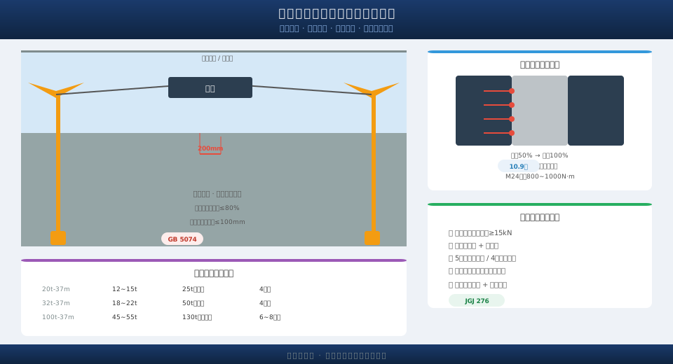
Pre-Hoisting Preparation Checklist
Before hoisting begins, the following preparations must be completed:
- Runway beam acceptance: Foundation acceptance passed and intermediate handover records submitted.
- Factory hoisting opening: Lifting opening or access path reserved in the factory building, with clearance meeting main girder entry requirements (main girder width + 500 mm minimum margin on both sides).
- Crane selection: Chosen crane must meet lifting capacity and lifting height requirements — the combined weight of main girder, lifting spreader, and rigging must not exceed 75% of the crane's rated lifting capacity.
- Lifting plan approval: Plan reviewed and approved by the supervision engineer and general contractor; dedicated safety officer present on site.
- Rigging inspection: Wire ropes and rigging pass visual inspection and remain within their valid service period.
- Certified operation: Crane operator and riggers hold valid certifications for their roles.
Before lifting, mark the crane bridge wheel mounting positions on the runway beams to enable rapid positioning once the main girder is set in place.
Reference lifting parameters for typical main girder capacities:
| Rated Lifting Capacity (t) | Main Girder Weight (t) | Recommended Hoisting Method | Min. Crane Capacity Required (t) |
|---|---|---|---|
| 10 | 3.5 – 5.5 | Single-crane lift | 16 |
| 16/3.2 | 5.5 – 8.5 | Single-crane lift | 25 |
| 20/5 | 7.5 – 11.5 | Single-crane lift | 32 |
| 32/5 | 12 – 18 | Dual-crane lift | 2 × 25 |
| 50/10 | 18 – 28 | Dual-crane lift | 2 × 40 |
| 75/20 | 28 – 42 | Dual-crane lift | 2 × 65 |
| 100/20 | 38 – 55 | Dual-crane lift | 2 × 80 |
Note: The above values are typical reference ranges. Actual parameters must be calculated based on the specific crane design, span, and site conditions.
Dual-Crane Main Girder Lifting Procedure
For main girders exceeding 15 t, dual-crane coordinated lifting is recommended. The two cranes are positioned at the designated lifting points on the main girder, with each crane's lifting points arranged symmetrically about the girder's center of gravity. The lifting capacity of each crane must cover no less than 60% of the main girder's weight. During the lifting process, the two cranes must maintain synchronized hoisting and travel speeds, with the speed difference controlled within 5%. A dedicated lifting commander coordinates the entire operation via walkie-talkie, ensuring both cranes maintain consistent speed and direction. Before lifting, a trial lift of 200–300 mm is performed to verify the stability of the rigging and the braking performance of both cranes.
High-Altitude End Carriage Assembly and Bolt Torquing
After the main girder is lifted to the installation position, the end carriages are hoisted separately and connected at height. The connection bolts must be tightened in a specific sequence — from the center of the connection joint outward, alternating left and right — to ensure uniform stress distribution across the joint. High-strength bolts must be tightened in two stages: initial tightening to 50% of the final torque, followed by final tightening to the specified torque value. After torquing, the bolt heads and nuts must be marked with a paint marker for inspection and acceptance. The crane rail gauge tolerance must be verified after assembly, with the deviation controlled within ±3 mm.
Safety Control Points for Crane Hoisting Operations
Key safety control points during the hoisting process include:
- Hoisting command: A dedicated lifting commander directs the entire operation; all signals must be clear and unambiguous.
- Safety zone: A warning zone is established directly below the lifting path, with no personnel permitted to stand or pass beneath the suspended load.
- Wind speed limit: Hoisting operations must stop when wind speed exceeds 10.8 m/s (Level 6 on the Beaufort scale).
- Night operations: Adequate lighting must be provided at the hoisting site and along the lifting path when working at night.
- Emergency plan: An emergency response plan must be in place before hoisting begins, covering scenarios such as crane failure, wire rope damage, and sudden weather changes.
