

Wire Rope Derailment in Electric Hoists: Causes & Fixes
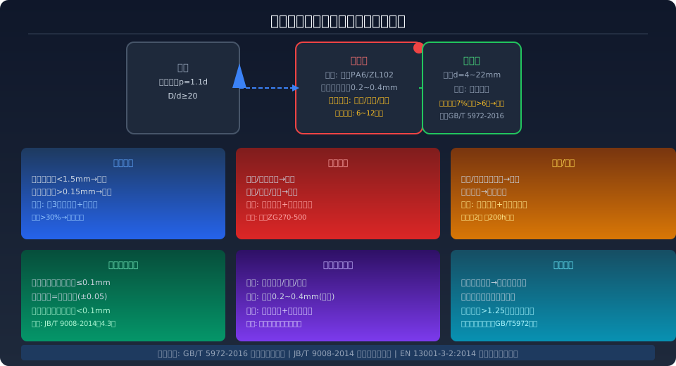
The Rope Guide is a critical component that ensures orderly wire rope winding on the drum. Common failure modes include excessive groove wear (wall thickness below 1.5 mm), mechanical fracture (pressure block/retaining ring), and seizure/jamming (due to inadequate lubrication or foreign particle ingress). Prevention hinges on precise installation (coaxiality within 0.1 mm), a scheduled inspection routine (daily + weekly + monthly checks), and proper operating practices (no angled lifting or overload). Reference standards: JB/T 9008-2014 and GB/T 5972-2016.
As the most widely used light-duty lifting equipment in industrial production, the electric hoist relies on its rope guide — also known as the rope deflector or rope presser — to keep the wire rope neatly layered on the drum and prevent crossover or derailment. Though it appears to be a simple component, the rope guide plays an indispensable role in safe and efficient hoisting operations. A damaged rope guide not only compromises productivity but can also lead to abnormal wire rope wear or even fracture, creating serious safety hazards. This article examines how the rope guide works, analyzes the root causes of its most common failures, and outlines a full range of preventive measures covering installation, operation, and routine maintenance.
The design and use of rope guides are governed by multiple national and industry standards. Per GB/T 5972-2016, "Specification for Inspection and Discard of Wire Ropes Used in Cranes," wire rope must be wound on the drum in an orderly manner, free from crossover, pinching, or derailment. Meanwhile, EN 13001-3-2:2014, "Crane Safety Standard — Wire Ropes and Pulley Systems," sets explicit design requirements for the structural strength and safety factor of rope guides. In addition, the JB/T 9008.1-2014, "Wire Rope Electric Hoists — Part 1: Types and Basic Parameters," series provides detailed technical specifications for clearance, material selection, and installation accuracy of rope guides.
How the Rope Guide Works and Why It Matters
Mounted on one side of the hoist drum, the rope guide directs the wire rope into the drum grooves in an orderly spiral pattern, preventing crossover and derailment. During hoisting or lowering, the rope guide travels synchronously with the drum rotation, pressing each wrap of wire rope firmly into the groove. The lead pitch of the rope guide must match the drum groove pitch precisely (within ±0.05 mm); any mismatch causes the guide to lag or advance, forcing the wire rope to press against the guide's side walls.
A typical rope guide assembly consists of a pressure block, guide rod, spring, and retaining ring. The pressure block is commonly made of nylon PA6 or cast aluminum ZL102, with cast steel ZG270-500 used for heavy-duty applications. The clearance between the guide's bore and the guide rod is held between 0.2 and 0.4 mm. Excessive clearance allows the guide to wobble and drift, accelerating groove wear; insufficient clearance can cause seizure due to thermal expansion or trapped debris. During operation, the rope guide is subjected to three simultaneous forces: the lateral component of the wire rope tension, the preload from the pressure block, and frictional resistance.
Common Rope Guide Failure Modes and Root Causes
Statistical analysis of customer feedback over the past three years by Kelude's after-sales maintenance department identifies three primary failure modes for rope guides — excessive wear, mechanical fracture, and seizure/jamming. Excessive wear accounts for the largest share at approximately 45% of all failures, followed by mechanical fracture at about 30%, seizure/jamming at roughly 20%, and other causes (such as manufacturing defects or material aging) at around 5%.
Excessive Wear — When the groove bottom wall thickness wears down to less than 1.5 mm, the rope guide's ability to control the wire rope diminishes noticeably, and the rope begins to wind irregularly. Once the bore ovality exceeds 0.15 mm, the guide develops a wobble on the rod, accelerating one-sided wear. The wear rate is closely tied to hoisting frequency, wire rope surface condition, and lubrication quality. In applications with frequent lifts (more than 200 cycles per day), rope guide service life can drop from 12 months to just 6–8 months.
Mechanical Fracture — The pressure block or retaining ring can fracture under impact overload, allowing the wire rope to jump out of the groove. This typically occurs in three scenarios: the hoisting mechanism continues running at its end limits, concentrating reverse tension on the rope guide; angled lifting creates lateral forces exceeding the guide's design strength; or forced correction after a derailment subjects the guide to abnormal loads. The risk is compounded when the wire rope diameter is oversized or the lay direction does not match the drum grooving.
Seizure and Jamming — The rope guide becomes stuck on the guide rod and can no longer follow the drum rotation. Common culprits include: metal filings, dust, or sand from the workshop environment entering the clearance between the rod and guide; dried-out or incorrectly specified grease increasing friction; or thermal deformation (temperatures can rise 60–80 °C during prolonged continuous operation) causing the guide to bind on the rod. If left unaddressed, the wire rope will repeatedly wind over the same spot, leading to localized excessive wear.
Rope Guide Failure Comparison: Types, Causes, and Prevention
The following table summarizes the characteristics, root causes, and preventive strategies for the three main rope guide failure modes, providing maintenance personnel with a quick diagnostic reference:
| Damage Type | Typical Characteristics | Root Cause | Determination Standard | Preventive Action |
|---|---|---|---|---|
| Wear Exceeding Limit | Groove Shallowing, Wire Rope Misalignment | Prolonged Friction, Lubrication Insufficiency, Soft Material | Insufficient Wall Thickness1.5mm; Ovality Exceeding0.15mm | Per3Monthly Wall Thickness Measurement+Ovality; Select Wear-Resistant PA6/ZL102 |
| Machinery Fracture | Clamping Block/Snap Ring Fracture, wire rope derailment | overload Impact, Oblique Lifting, Correction After Rope Jump | Visually Detectable Crack Or Fracture | Install Limit switch+Anti-Jump Device; Prohibit Oblique Lifting and Overload |
| Seizure and Locking | Rope Guide Sliding Obstruction, Wire Rope Local Rewinding | Foreign Object Intrusion, Grease Dry-Out, Heat Deformation Binding | Manual Significant Increase in Push Resistance | Weekly Foreign Object Cleaning+Replenish Lithium grease2Grade; Per200hAdd |
4 Key Preventive Actions to Avoid Rope Guide Failure
Installation Accuracy Control — Installation accuracy is the first line of defense against rope guide damage. The coaxiality between the rope guide and the drum must be held within 0.1mm, and the deviation between the lead screw pitch and the drum groove pitch must not exceed ±0.05mm. Use a dial indicator to check the straightness of the guide rod during installation, which must not exceed 0.08mm over its full length. The preload on the rope guide clamp block should follow the manufacturer's specified torque value (typically 15–25 N·m); over-tightening increases friction, while under-tightening reduces rope-holding effectiveness. After installation, perform at least five full no-load hoisting cycles to verify that the wire rope spools evenly and neatly.
Routine Inspection Schedule — A three-tier inspection system is an effective way to extend rope guide service life. Daily checks rely primarily on visual inspection, focusing on cracks, deformation, or abnormal wear marks on the rope guide surface, while listening for unusual friction or vibration noises during operation. Weekly checks use a feeler gauge to measure the clearance between the rope guide bore and the guide rod, with a standard value of 0.2–0.4mm, and verify that the fixing bolts have not loosened. Monthly checks include measuring the rope guide wall thickness (using an ultrasonic thickness gauge or optical flat), re-checking guide rod straightness, and cleaning and replacing the grease. All inspection data should be recorded in the equipment maintenance log to analyze wear trends and predict the replacement interval.
Lubrication Management — Proper grease selection and regular replenishment are critical to preventing rope guide jamming. Lithium-based grease No. 2 is recommended (working temperature range: -20°C to 120°C / -4°F to 248°F), with re-greasing every 200 operating hours or weekly. Before re-greasing, clean old grease and debris from the guide rod surface to prevent lubrication failure caused by mixing old and new grease. In high-temperature workshops (ambient temperature consistently above 40°C / 104°F) or in dusty casting workshops, the lubrication interval should be shortened to every 100 operating hours. Using waste oil or standard grease as a substitute for the specified grease is strictly prohibited.
Certified Operation Training — Improper operator handling is a major human factor contributing to rope guide damage. Angled lifting or pulling (any wire rope angle exceeding 5° from vertical) is strictly prohibited, as the lateral force generated can subject the rope guide to loads several times higher than normal operating conditions. The hoisting limit switch must remain sensitive and functional to prevent the hook from striking the top and causing concentrated reverse tension on the wire rope. Overloading beyond 1.25 times the rated lifting capacity is strictly forbidden — overloading not only compromises wire rope safety but also indirectly transfers increased tension to the rope guide. All operators must complete specialized training and hold valid certification.
Rope Guide Replacement & Installation Technical Requirements
When a rope guide reaches its discard criteria and requires replacement, the installation process must strictly follow the technical requirements below. First, verify that the new rope guide model matches the drum specification, and that the lead screw pitch is consistent with the original drum groove pitch (common pitches: 6mm, 8mm, 10mm, and 12.5mm). Before installation, check that the guide rod surface roughness (Ra) does not exceed 1.6μm; if corrosion or scratches are present, polish the surface smooth with fine sandpaper. The rope guide clamp block must be installed in the correct orientation, with the arc surface matching the wire rope outer diameter.
Rope Guide Installation Technical Parameters Reference Table
| Inspection Item | Technical Requirement | Detection Method | Standard Basis |
|---|---|---|---|
| Coaxiality | Not Exceeding0.1mm | dial indicator Measure Both Ends and Middle of Guide Rod | JB/T 9008-2014Clause4.3Item |
| Fit Clearance | 0.2To0.4mm | Feeler Gauge Measurement of Diameter Difference Between Bore and Guide Rod | JB/T 9008.2-2014 |
| Guide Rod Straightness | Full Length Not Exceeding0.08mm | dial indicator Sliding Measurement Along Full Length of Guide Rod | ISO 4301 Crane Design Standard-2008 |
| Clamping Block Preload | 15To25Nm | Torque Wrench per Manufacturer | Manufacturer |
| Lead Matching | Equal to Rope Groove Pitch(±0.05mm) | Comparison Rope Guide Specification With Drum Parameter | Manufacturer Specification Manual |
After installation is complete, run at least five full-travel no-load hoisting cycles to verify that the rope guide travels smoothly and the wire rope spools evenly. Listen for any abnormal noise during testing. The first load test should be performed at 50% of the rated load; only after confirming proper operation should a full-load test be conducted. The first 100 operating hours of a new rope guide constitute the break-in period, during which the fit clearance and lubrication condition should be checked daily, with adjustments made promptly if any abnormality is detected.
Kelude recommends using genuine factory rope guides. All components undergo strict quality and dimensional inspection to ensure precise matching with the drum. The factory rope guide is manufactured from PA6 reinforced with 30% glass fiber, offering excellent wear resistance and dimensional stability, with a service life of over 12 months under normal operating conditions.
Rope Guide Replacement: Common Questions Answered
Q: At what wear level must the rope guide be replaced? Is there a clear quantitative standard?
A: The rope guide must be replaced immediately when the groove bottom wall thickness wears to less than 1.5 mm. Also check the ovality of the bore — if it exceeds 0.15 mm, the rope guide has developed uneven wear and should be replaced even if the wall thickness is still within limits. Additionally, replacement is required when visible cracks appear on the pressure block or retaining ring, when the guide rod fit clearance exceeds 0.6 mm (standard range: 0.2–0.4 mm), or when the wire rope repeatedly jumps the groove and adjustments fail to resolve the issue. These criteria align with the relevant provisions of JB/T 9008.2-2014, the technical specification for wire rope electric hoists.
Q: Can the rope guide be machined locally, or must it be a factory replacement part?
A: Local machining is not recommended. The lead pitch of the rope guide must precisely match the drum groove pitch (permissible deviation is only ±0.05 mm), and the material must meet the strength requirements of PA6 with 30% glass fiber reinforcement or ZL102 cast aluminum. Standard machining processes generally cannot achieve the required accuracy and material properties. Using a non-genuine or mismatched rope guide can cause delayed rope feeding, side-wall compression of the rope guide by the wire rope, or even fracture. Kelude offers the full range of genuine rope guides for all electric hoist models, along with installation guidance services.
Q: Is rope guide damage related to wire rope selection and maintenance?
A: Yes, the relationship is significant. An oversized wire rope (exceeding 105% of the drum's design rope diameter) increases the pressing resistance on the rope guide and accelerates groove wear; an undersized rope may cause groove jumping. A mismatched rope lay direction (e.g., using a left regular lay wire rope on a drum groove designed for right-hand lay) also subjects the rope guide to additional torque. Furthermore, poor wire rope lubrication leading to surface corrosion and roughness will accelerate rope guide wear. Regular inspection and maintenance in accordance with GB/T 5972-2016, the specification for inspection and discard criteria of crane wire ropes, can effectively reduce the risk of rope guide damage.
Q: How can abnormal rope guide operation be detected during daily electric hoist use?
A: Abnormal rope guide operation typically shows the following signs: a rhythmic clicking sound during operation (indicating interference between the pressure block and the wire rope); wire rope crossover, localized piling, or uneven spacing on the drum; noticeable lateral sway of the wire rope during hoisting; or unusual bright wear bands or scratches on the guide rod surface. If any of these signs appear, stop the hoist immediately and inspect the rope guide, focusing on fit clearance and wall thickness measurements. Early detection and correction can prevent the serious consequence of complete rope guide failure leading to wire rope derailment.
Kelude offers genuine rope guides for the full range of electric hoists, covering CD1, MD1, HC, and other wire rope electric hoist models, with one-stop technical support from selection guidance and installation assistance to scheduled maintenance services.
