

Electric Hoist Not Responding to Button? 5-Step Fault Diagnosis
When an electric hoist does not respond at all after the pendant button is pressed, it is one of the most common electrical faults in daily crane operation. Troubleshooting should follow a six-level progressive approach: power supply, protection devices, contactors, motor, control circuit, and mechanical drive. Key diagnostic points: three-phase supply voltage must not drop below 340V, control transformer output should be 36V, contactor coil resistance should be no less than 100 ohms with clean contacts, motor insulation resistance should be at least 0.5M ohms, and the motor must rotate freely when turned manually. This article references the ISO 4301 Crane Design Standard, TSG Q7015-2016 inspection rules, and JB/T 9008.5-2020 product standard, providing a complete fault tree with measured parameters.
Diagnosing a non-responsive electric hoist requires reference to Chapter 6 of ISO 4301 Crane Design Standard covering electrical control system design, as well as the electrical safety device inspection clauses in TSG Q7015-2016 Rules for Periodic Inspection of Lifting Appliances. The hoist itself must also comply with the electrical control and protection requirements specified in JB/T 9008.5-2020 Wire Rope Electric Hoist — Part 5.
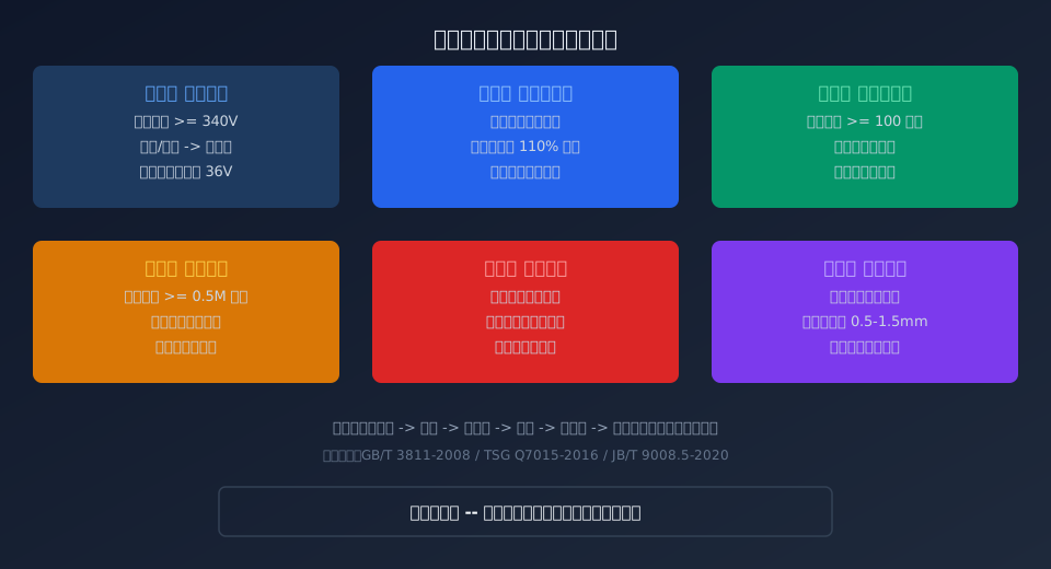
How to Troubleshoot an Electric Hoist That Won't Respond to the Pendant
When an electric hoist fails to respond after pressing either the hoisting or lowering button, an open circuit exists in the main circuit or control circuit. Follow the principle of "simple to complex, external to internal" and diagnose across six levels.
Level 1: Power Supply Input Check. Using a multimeter set to AC 750V, measure the three-phase voltage at the conductor rail or trailing cable entry point. The normal range is 380V ±10% (i.e., 342V to 418V). If the voltage between any two phases is below 340V, excessive line voltage drop or insufficient transformer capacity is indicated. A phase-loss condition will prevent the hoist from operating — check the upstream circuit breaker and line joints.
Level 2: Emergency Stop and Protection Circuit. Verify that the emergency stop button is not pressed in, as pressing it cuts power to all control circuits. To reset, rotate the mushroom-head button clockwise until it pops back out. Also check whether the overload limiter has tripped. When the actual load reaches 110% of the rated load, the limiter automatically cuts the hoisting circuit; unload the hoist and press the reset button to clear the fault.
Level 3: Contactor Operation Test. Listen for the contactor's characteristic "click" when the button is pressed. If no sound is heard, measure the coil resistance across the contactor terminals with a multimeter in resistance mode. Normal readings should be no less than 100 ohms. A reading of 0 ohms indicates a shorted (burned-out) coil; infinite resistance indicates an open coil. New contactor coils are typically rated at 36V or 380V and must match the control transformer output.
Level 4: Motor Inspection. With power disconnected, rotate the motor cooling fan by hand. If it is completely locked, the motor bearing has seized or the brake has failed to release. Using a 500V megohmmeter (insulation tester), measure the insulation resistance of the motor windings to ground — it must be no less than 0.5M ohms. The DC resistance imbalance between the three-phase windings should not exceed 2%; readings above 5% indicate turn-to-turn short circuits.
Level 5: Control Circuit Check. Pendant buttons are wear parts — cracked housings or water ingress cause contact oxidation and poor conductivity. Use the multimeter's continuity buzzer mode to test each button individually; resistance when pressed should not exceed 1 ohm. Burned intermediate relay contacts can also interrupt control signal transmission.
Level 6: Mechanical Drive Inspection. Mechanical faults such as a jammed reducer gear (broken teeth or foreign object), a broken brake spring preventing the brake pads from releasing, or wire rope cross-winding and jamming on the drum can all stall the motor and prevent startup. These faults are often accompanied by a humming noise from the motor or a tripped circuit breaker.
4 Common Causes of a Non-Engaging Contactor and How to Test Them
The contactor is the core actuating element in the hoist control circuit — if it fails to engage, the motor receives no power. According to Kelude after-sales maintenance data, contactor faults account for approximately 35% of all hoist no-response cases. Below are the four most frequent failure modes with their diagnostic procedures.
Cause 1: Burned-Out Coil. Prolonged energization or abnormal voltage causes insulation aging and breakdown. Measure coil resistance with a multimeter: normal range is 100 to 500 ohms (depending on power rating); a burned coil reads 0 ohms or infinite resistance. When replacing the coil, the voltage rating must match the original — 36V, 220V, or 380V.
Cause 2: Stuck Armature Core. Dust or metal filings entering the core contact surfaces cause mechanical jamming. The symptom is a faint vibration from the contactor when the button is pressed, but the armature fails to pull in fully. Remedy: remove the contactor, clean the core faces with anhydrous alcohol, and verify smooth manual push-pull operation before reinstalling.
Cause 3: Burned or Welded Contacts. Repeated load breaking causes surface oxidation, blackening, or welding of the contacts. Main contact resistance should not exceed 100 micro-ohms; if it exceeds 200 micro-ohms, dress or replace the contacts. All three main contact sets must close simultaneously, with a synchronization error no greater than 0.5mm.
Cause 4: Control Transformer Fault. Insufficient output voltage (below 32V) or a burned-out transformer fails to provide the working voltage required by the contactor coil. The BK-100 control transformer (100VA) is a common model for electric hoists, with a 36V secondary output and dual 380V/220V primary inputs.
Contactor Model Comparison: 6 Options for Electric Hoist Applications
| Model | rated current(A) | Suitable for Hoist Capacity |
|---|---|---|
| CJX2-0910 | 9A | 0.5tto1t |
| CJX2-1210 | 12A | 2tto3t |
| CJX2-1810 | 18A | 5t |
| CJX2-2510 | 25A | 10tto16t |
| CJX2-3210 | 32A | 20t |
| CJX2-4011 | 40A | 32tand Above |
Electric Hoist Electrical Component Inspection Standards & Acceptance Criteria
| Inspection Item | Standard Requirement | Non-conformance determination |
|---|---|---|
| Three-phase Power Supply Voltage | 342Vto418V | Below340Vor above430V |
| Motor Insulation Resistance | Not less than0.5Mohm | Below0.5Mohm |
| Contactor Coil resistance | 100ohm to500ohm | 0ohm or infinity |
| Control Transformer Output | 36VTolerance5% | Below32Vor above40V |
| Three-phase winding unbalance | Not exceeding2% | Greater than5% |
| Overload protection trip setting | 100%to110%Full Measuring Range | Greater than110%or less90% |
Why Does a Crane Hoisting Motor Hum but Not Rotate When Powered On?
A humming motor that fails to rotate is a classic locked-rotor condition, indicating that power has reached the motor windings but the rotor cannot turn. Based on years of field diagnostics by the Kelude technical team, this fault typically stems from three root causes.
Cause breakdown:
(1) Mechanical seizure: Broken gear teeth from the reducer can jam the gear mesh, drum bearings can seize, or a wire rope derailment can wedge the rope in the end clearance of the drum — all of which lock the drive train. In such cases, the motor's starting current can reach 5 to 7 times its rated value, and if power is not cut promptly, the windings will burn out within 30 seconds.
(2) Brake fails to release: The Conical Rotor Motor brake relies on axial rotor thrust to push the brake plates apart. When the Brake Spring preload is excessive (clearance below 0.5mm), the brake plates and drum are seized by corrosion, or conical surface wear reduces axial travel, the brake cannot disengage properly.
(3) Loss of one phase in the power supply: When one phase of a three-phase supply is missing, the motor produces a pulsating magnetic field rather than a rotating one, so the rotor cannot start and a low hum is emitted. Power must be cut immediately; otherwise, the windings will rapidly exceed the Class F insulation temperature limit of 155°C.
Diagnostic procedure:
First, de-energize the unit and manually rotate the shaft to confirm the drive train is not mechanically locked.
Next, measure the Brake Clearance using a feeler gauge (standard range: 0.5 to 1.5mm).
Finally, use a multimeter to check voltage phase-by-phase at the power supply inlet and the motor wiring terminals.
3 Trigger Conditions for Frequent Overload Limiter False Trips on Electric Hoists & Calibration Reset Guide
The Overload Limiter is the core safety protection device on an Electric Hoist. When false trips cause repeated power cuts under normal loads, investigate three areas: sensor zero drift, load calibration shift, and mechanical binding.
Trigger condition 1: Sensor zero drift. Resistance strain-gauge sensors develop zero-point offset after temperature fluctuations or prolonged loading. With power off, measure the sensor's zero-output signal — it should read 0mV ± 0.05mV. ISO 4301 specifies that the comprehensive accuracy of the Overload Limiter must not exceed ±5% of full scale.
Trigger condition 2: Load calibration shift. If the limiter's calibration is not properly stored after reset, or if instrument parameters are corrupted by electromagnetic interference, the protection threshold may drop below the normal Lifting Capacity. Recalibrate using Standard Weights or a calibrated tension meter, typically at 90% and 110% of the rated load.
Trigger condition 3: Mechanical binding of the sensor. Excessive wear in the pin bore of a pin-type sensor, or loose Fixing bolts on a plate-ring sensor, alters the load path and distorts the force signal received by the sensor. This requires reinstalling the sensor and applying the specified Preload torque.
5 Critical Test Points for Electric Hoist Control Wiring & Standard Voltage Readings
Faults in Electric Hoist control wiring most often occur at Terminal Blocks and wear-prone components. Kelude After-Sales Service data shows that roughly 40% of no-action faults trace back to control circuit issues rather than the motor or Reducer. Below are the five critical test points with their standard parameters.
Test point 1: Main power supply inlet terminals (L1, L2, L3). Using the multimeter's AC 750V range, phase-to-phase voltage should read 380V ±10%, and each phase to neutral (N) should read 220V ±10%.
Test point 2: Control Transformer primary (380V input). Voltage should match the main supply. Secondary (36V output) should read 36V ±5%. Transformer capacity is typically 100VA (Model BK-100).
Test point 3: Emergency Stop Button normally-closed contacts. When not pressed, resistance should not exceed 1 ohm (closed circuit); when pressed, it should read infinite (open circuit). Oxidized contacts increase contact resistance and cause Voltage drop — when the 36V control voltage drops below 28V, the Contactor will not pull in.
Test point 4: Pendant button output terminals. When the Hoisting or Lowering button is pressed, the corresponding output terminal-to-common voltage should jump from 0V to 36V. If no jump occurs, the button contacts are faulty or the control line is open.
Test point 5: Contactor coil terminals A1 and A2. With the button pressed, the coil should receive 36V (or 380V, depending on the Model). Voltage present but no pull-in indicates a burned coil or seized iron core; no voltage indicates an open control circuit.
Three-Phase Supply Normal Range
342 to 418V
380V ±10%
Minimum Motor Insulation
0.5 MΩ or higher
Measured with 500V Megohmmeter
Contactor Coil Resistance
100 to 500 ohms
Measured with multimeter resistance range
Control Transformer Output
36V ±5%
Model BK-100 Transformer
Brake Clearance Standard
0.5 to 1.5mm
Feeler gauge method
Overload Protection Threshold
110% of Full Scale
Rated load × 1.1
Related Reading: Expanded Resources on Crane Electrical Fault Diagnosis
This article focuses on troubleshooting Electric Hoist no-action faults. If you'd like to explore diagnostic techniques for other common crane electrical issues, the Kelude technical team recommends the following articles:
- How to Troubleshoot and Prevent Crane Hoisting Motor Burnout? 7 Fault Causes, Temperature Rise Standards & Full Analysis
- KBK Electric Hoist Motor Frequently Burning Out? 7 Causes, Temperature Rise Standards & Protection Solutions
- Crane Travel Mechanism Installation & Commissioning Guide: 5 Parameter Standards and 6 Common Problem Solutions
- How to Inspect Crane Wire Rope for Broken Wires, Wear and Deformation? 6 Discard Standards & Daily Inspection Guide
Frequently Asked Questions
Q: What causes frequent contactor burnout in an electric hoist?
A: There are three primary causes of repeated contactor failure. First, a coil voltage mismatch — for example, connecting a 36V coil to a 220V supply — which can destroy the contactor in under one second. Second, foreign matter on the iron core mating surfaces increases magnetic circuit reluctance, driving coil current to 1.5 to 2 times the rated value. Third, excessive jogging frequency: when inching operations exceed 300 cycles per hour, the contactor temperature rise surpasses the 80K limit for Class B insulation. Kelude recommends specifying contactors with a 20% capacity margin and installing an RC snubber (0.1 µF capacitor in series with a 100 Ω resistor) to suppress switching overvoltages.
Q: What electrical protection inspection requirements does TSG Q7015-2016 impose on electric hoists?
A: Clause B6 of TSG Q7015-2016, the Periodic Inspection Rules for Lifting Appliances, requires electric hoists to be equipped with undervoltage protection (no automatic restart after power restoration), zero position protection (the hoist only responds after the pendant is returned to neutral and re-operated), and overcurrent protection (thermal overload relay set at 1.0 to 1.1 times the motor's rated current). Clause B8 mandates that the overload limiter trip within 90% to 110% of the rated load, and that the limiter reliably cut off the hoisting circuit during a 130% static load test. Inspection intervals: initial inspection after installation, then every two years thereafter.
Q: What is the difference between a hoist that hums but does not lift and one that does not respond at all?
A: The two conditions point to entirely different fault locations. A humming sound indicates that the main circuit is energized and the contactor has pulled in — the fault lies on the motor rotor side or in the mechanical drive train (brake not releasing, gearbox seized, or a missing phase in the power supply). No response at all means the main circuit is not energized — the fault is in the control circuit (emergency stop, pushbutton, contactor coil, or control transformer). Diagnostic approach: if the hoist hums, use a clamp meter to measure the starting current (stall current runs 5 to 7 times the rated value); if silent, check control circuit voltage stage by stage.
Q: How much does it typically cost to repair a non-functioning electric hoist?
A: Repair costs vary significantly depending on the fault type. For simple issues such as resetting the emergency stop or replacing a pushbutton, parts run $5–$12 and labor $30. Replacing a contactor (CJX2-1210): parts $12–$22, labor $45. Replacing a control transformer (BK-100): parts $18–$30, labor $45. Replacing a hoisting motor (0.8 kW conical rotor): parts $120–$220, labor $75. Kelude offers on-site diagnostic service nationwide, starting at $30 for the inspection, and repairs are only carried out after a fault diagnosis report is issued.
This article was prepared by the Kelude Heavy Industry technical team in accordance with ISO 4301, TSG Q7015-2016, JB/T 9008.5-2020 and other applicable standards. Always de-energize the equipment and follow lockout/tagout procedures before servicing. Only certified electricians may work on circuits above 380V.
