

Overhead Crane Anti-Collision System for Multi-Crane Same-Span
Anti-Collision for Multiple Cranes on the Same Runway: LiDAR + PLC Interlock + Zone Limit Are All Essential. Operating multiple overhead cranes on the same runway is a key strategy for boosting workshop productivity, but it multiplies the risk of collision. When two or more cranes travel independently on the same rail, any lapse in maintaining safe separation can lead to anything from minor scrapes and damage to structural deformation or even a fall. Traditional travel limit switches or operator visual checks are no longer sufficient to ensure safe multi-crane coordination.
Running multiple cranes on the same runway is essential for maximizing workshop throughput, yet it proportionally increases the risk of collision. When two or more overhead cranes operate independently on a shared rail, inadequate safe spacing can result in anything from minor scrapes to structural deformation or even a catastrophic fall. Conventional travel limit switches or operator line-of-sight methods are no longer adequate for the safety demands of coordinated multi-crane operation. Drawing on Kelude Heavy Industry's experience in designing anti-collision systems for non-standard cranes, this article details the engineering implementation of core technologies including LiDAR zone scanning, PLC interlock logic, mechanical zone limit stops, millimeter-wave radar redundancy, and multi-crane coordinated scheduling. All technical parameters comply with ISO 4301 (Crane Design Standard) and ISO 4309 (Safety Code for Lifting Appliances).
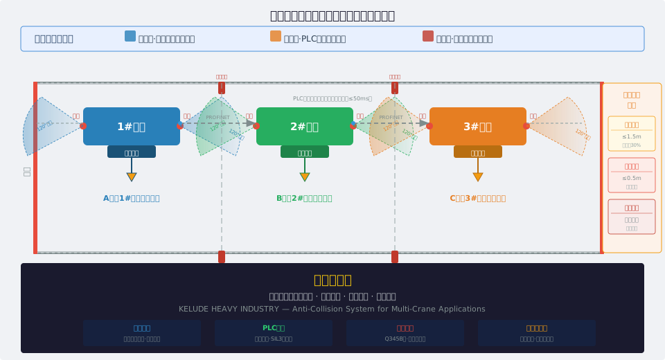
Collision Risk Analysis for Multiple Cranes on a Shared Runway
Collision risks among multiple cranes on the same runway are inherently complex. In the spatial dimension, the safe separation distance between two cranes traveling toward each other depends directly on travel speed, braking distance, and reaction time. Per ISO 4301 Section 5.4.2 on braking distance for travel mechanisms, at a rated speed of 80 m/min, the crane bridge braking distance is approximately 5.3 m. Adding the operator's average reaction time of 0.3 to 0.5 seconds—corresponding to a coasting distance of 0.4 to 0.7 m—the minimum safe separation should not be less than 6 m. When three or more cranes operate within the same span, the middle units are exposed to threats from both sides, and the risk escalates quadratically. From an equipment standpoint, data from ISO 4309 on crane brakes indicates that electromagnetic disc brakes experience an 8% to 15% decay in braking torque after 2,000 hours of continuous use. In older factory buildings, over 30% of crane rail sections exhibit straightness deviations exceeding ±5 mm per 10 m, with cumulative running offsets reaching ±20 mm. On the human factors side, when visibility in dusty or misty workshops drops below 5 m, operator error accounts for over 65% of collision incidents. A three-dimensional anti-collision system integrating sensor detection, logic interlock, and physical isolation is therefore essential.
LiDAR Zone Scanning for Crane Anti-Collision
LiDAR serves as the first line of active protection in non-standard anti-collision systems. The following breaks down the core technical specifications across three dimensions: hardware parameters, a three-tier warning mechanism, and installation requirements.
Field of View: 270° horizontal / 30° vertical
Scan Frequency: 25–50 Hz
Angular Resolution: 0.09°–0.18°
Points per Frame: ~1,500 measurement points
Range Accuracy: ±30 mm @ 50 m
Angular Accuracy: ±0.1°
Alarm Type: 1 Hz intermittent audible and visual alarm
Sound Pressure Level: ≥85 dB
Lighting: Yellow rotating warning light
PLC: Logs alarm events to history
Auto Speed Reduction: Down to 30% of rated speed
Example: 80 m/min → 24 m/min
Acceleration Control: 0.2–0.3 m/s²
Execution: Automatic frequency adjustment via VFD
PLC Action: Emergency stop command
Braking Method: DC injection braking + electromagnetic disc brake
Braking Time: 1.5–2.5 s for full travel stop
Location: Outer side of end carriage, 300–500 mm above crane rail
Applicable Span: ≥30 m
Ultrasonic Blind-Zone Coverage: One sensor at each of the four bottom corners (0.3–3 m)
Protection Rating: IP67
Recommended Wavelength: 1550 nm (3–5× better penetration than 905 nm)
Protection Rating: IP67
Cleaning: Automatic air-curtain system
Application: Foundry, cement, and mining workshops
PLC Interlock Logic Design
PLC interlocking is the decision-making core of anti-collision systems for multiple cranes operating on the same runway. Each crane is equipped with a SIL3-rated safety PLC, and all PLCs are connected in a ring topology via PROFINET. A single-point network failure self-heals in ≤50 ms. The data exchange cycle is 20 ms, with each PLC broadcasting its own position coordinates (accuracy ±1 mm), speed (accuracy 0.1 m/min), travel direction, and equipment status. Interlock decisions use a dual-arbitration scheme combining zone priority and distance priority. Zone priority divides the runway into logical partitions, allowing only one crane per partition at any given time; the minimum partition length equals the braking distance at rated speed multiplied by a 1.5 safety factor. Distance priority calculates the time-to-collision (TTC) as the current gap divided by the relative speed (when relative speed is greater than zero). A TTC of less than 10 seconds triggers deceleration, and a TTC of less than 5 seconds triggers emergency stop. For example, two cranes approaching each other with a 15 m gap and a relative speed of 1.5 m/s (90 m/min) yield a TTC of 10 seconds, triggering deceleration; when the gap narrows to 7.5 m, the TTC drops to 5 seconds, triggering a stop. The PLC allows operators to set a work priority level (1 to 5, with 1 being the highest) via the HMI. Higher-priority cranes have precedence for zone occupancy, while lower-priority cranes automatically stop and wait outside the safety boundary. Priority preemption response time is ≤100 ms. All interlock events are recorded in a local 10,000-entry buffer and uploaded to the central control system via OPC UA.
Mechanical Zone Limit Stops
Mechanical zone limit stops serve as the final physical barrier in the anti-collision system. In strict compliance with Clause 5.4.8 of ISO 4301 Crane Design Standard regarding travel limit switches, Kelude ensures that both ends of the travel mechanism on every crane are fitted with travel limit switches that work in conjunction with the buffer stops at the runway ends. In custom-engineered solutions, these stops are also deployed at partition boundaries to provide physical zone isolation. The stops feature a wedge-shaped buffer structure with a Q345B steel body (≈S355J2) and a 20 mm thick polyurethane buffer pad (Shore hardness 80A ±5A) welded to the front face, capable of absorbing 3,000 J of impact energy per event. Each stop is secured to the embedded plate at the base of the crane rail using four 8.8-grade M20 bolts, with a perpendicularity deviation of ≤1 mm. A dual-redundant travel limit switch (one normally open and one normally closed contact in series) is mounted on the side. When the end-carriage bumper is 50 to 80 mm from the stop, the travel switch is triggered first, sending a stop command to the PLC. If the switch fails, the bumper makes direct contact with the buffer pad, which allows a maximum compression stroke of 30 mm at a maximum allowable impact speed of 0.5 m/s. The spacing between stops equals the crane length plus the working travel plus a 100 mm safety margin at each end. For a general purpose bridge crane with a 22.5 m span and a 6 m long bridge, the stop spacing is 18.2 m for a 12 m effective travel. The top of each stop is painted with yellow-and-black warning stripes (100 mm wide, 45° diagonal, in accordance with GB 2893) and fitted with reflective tape for nighttime visibility.
Millimeter-Wave Radar Dual Redundancy
Millimeter-wave radar provides sensing redundancy to the LiDAR-based solution. Using 77 GHz or 79 GHz frequency-modulated continuous wave (FMCW) technology with a wavelength of approximately 3.9 mm, it offers exceptional penetration through dust and moisture.edundancy to the LiDAR-based solution. Using 77 GHz or 79 GHz frequency-modulated continuous wave (FMCW) technology with a wavelength of approximately 3.9 mm, it offers exceptional penetration through dust and moisture. In extreme dust conditions where visibility drops below 1 meter, millimeter-wave radar detection performance degrades by only 10% to 15%, whereas LiDAR can degrade by more than 50%. Key parameters: maximum detection range of 80 to 120 meters (depending on target RCS), distance accuracy of ±0.2 m (±0.1 m in high-precision mode), velocity accuracy of ±0.05 m/s, horizontal field of view of ±60° to ±90°, and update rate of 20 to 50 Hz. The Doppler effect enables direct measurement of target radial velocity, improving TTC calculation accuracy by 30% to 40%. Redundancy is achieved through dual-sensor fusion with an automatic switching strategy. In normal mode, a Kalman filter fuses data from both sensors to output combined information. When the LiDAR received light intensity falls below the threshold, point-cloud density drops below 50% of normal, or the ambient temperature goes outside the −10 °C to +55 °C range, the system automatically switches to millimeter-wave radar single-sensor mode with a switching time of ≤100 ms. After switching, the warning distances are adjusted from 50/20/5 m to 50/25/8 m. Once the LiDAR recovers, the system automatically restores dual-sensor fusion after three consecutive fault-free data cycles (approximately 150 ms).
Four-Level Anti-Collision Solutions: Technical Comparison
LiDAR zone scanning, PLC interlock logic, mechanical limit stops, and millimeter-wave radar dual redundancy each offer distinct application scenarios and technical characteristics. The following comparison evaluates these four anti-collision solutions across six dimensions — detection principle, coverage range, response time, reliability, applicable conditions, and cost — to support engineering selection decisions.
| Comparison Parameter | Li DAR scanning | PLCInterlock Logic | Machinery Limit stop | mm Wave radarredundancy |
|---|---|---|---|---|
| Detection Principle | TOFLaser pulse120Degree sector scan | Hardwired signal+Relay Dual arbitration algorithm | Machinery Contact+Travel Switch / Proximity Switch Pure physical isolation | 77GHz FMCWBeam angle ±5deg |
| Detection Distance | 0.5~30mAdjustable sector Angle | Not signal-based; safety zone must be defined | Contact-type0mm Travel Switch / Proximity Switch Advance50~200mm | 0.2~40mPenetrates dust, rain, and fog |
| Response time | ≤50ms | ≤20ms+10ms Relay | ≤15ms Instantaneous irreversible collision | ≤60ms |
| Environmental adaptability | Dust susceptibility/Bright light interference/Rain/fog attenuation | Unaffected by environment/All-weather/Maintenance-free | Completely immune to environmental conditions/Requires manual reset | Penetrates dust, rain, and fog/All-weather/False alarm from metal reflection |
| Application Scenarios | Clean indoor Workshop/Large-area coverage Monitoring | All operating conditions/Standard on core safety circuit | Crane Rail Final protection at both ends/Maintenance scenario | Outdoor dust and high temperature/Li DARFailureredundancy |
| Cost per crane | Medium 0.8~1.510k CNY | Low 0.2~0.510k CNY | Lowest 0.1~0.310k CNY | High 1.5~3.010k CNY |
| Recommended protection level | Level 1 – Active protection | Level 2 – Logic protection | Level 3 – Physical protection | Dusty Environment Service Alternative solution |
Integrated Control Cabinet Solutions
The integrated control cabinet serves as the central hub for the anti-collision system. Kelude Heavy Industry offers a standard cabinet configuration measuring 1200mm (H) × 800mm (W) × 400mm (D), constructed from 1.5mm cold-rolled steel plate with electrostatic powder coating in RAL7035. The cabinet provides IP54 protection as standard, with IP65 recommended for dust-heavy workshop environments. Internally, the cabinet features a tiered layout: the upper tier houses the PLC and safety relays, the middle tier accommodates VFDs and network switches, and the lower tier contains circuit breakers and switching power supplies. Cooling channels between tiers, combined with a roof-mounted axial fan (airflow ≥200m³/h), ensure proper heat dissipation. A temperature control switch automatically activates the fan when internal temperatures exceed 40°C. The electrical architecture uses 24V DC for the control circuit, while the main circuit operates on 380V AC/50Hz three-phase five-wire. A 500VA UPS maintains system operation for ≥30 minutes during power outages. EMC-shielded signal cables are routed with a minimum separation of 100mm from power lines, and grounding resistance is maintained at ≤4Ω. A du/dt filter on the VFD output side limits peak voltage to within 1.15 times the rated value. The HMI features a 10-inch color touch screen (1024×600 resolution, brightness ≥350cd/m²) displaying real-time anti-collision system status, individual crane position and speed, radar detection visualization, zone occupancy overview, and a 24-hour alarm timeline. Parameter configuration is protected by three access levels (Operator, Maintenance Engineer, System Administrator), with all parameter modifications logged and retained for ≥180 days. Expansion interfaces include 2 Gigabit RJ45 ports, 1 RS485 port, 4 digital inputs (24VDC), and 4 digital outputs (250VAC/5A).
