

JB/T 9004 Crane Trolley Specifications and Acceptance
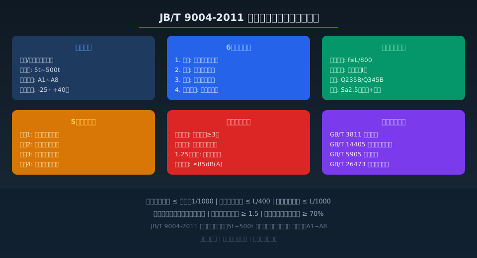
JB/T 9004-2011 "Crane Trolleys" is the core industry standard governing the design and manufacturing of trolleys for bridge and gantry cranes. It specifies technical requirements for the trolley frame structure, wheel assemblies, hoisting mechanism, and travel mechanism, as well as assembly tolerances, test methods, and acceptance criteria. The standard applies to trolleys with rated lifting capacities from 5t to 500t and work classifications A1 to A8 for bridge and gantry cranes, covering the complete chain of technical requirements from material selection to factory acceptance testing. This article breaks down the six key design parameters and five-step assembly acceptance procedures based on the standard, helping engineers quickly master the essentials of trolley selection and design.
What Standards Govern Crane Trolley Design and Manufacturing?
The design and manufacturing of crane trolleys involve multiple levels of national and industry standards that form a complete technical specification framework. Before starting the trolley design, engineers need to establish the following standard references:
1. Fundamental design code. As a core component of the crane, the trolley's overall design must comply with the general requirements of GB/T 3811-2008 "Crane Design Standard" regarding load combinations, work classification, and allowable stress verification. This standard defines the two-dimensional classification method based on utilization class U0–U9 and load spectrum Q1–Q4, which serves as the overall basis for wheel load calculations and structural strength verification.
2. Product-specific standard. JB/T 9004-2011 "Crane Trolleys" is the direct technical specification at the product level, covering frame structure dimensional tolerances, wheel assembly accuracy, mechanism matching requirements, and factory test procedures. This standard is consistent with the trolley-related requirements in GB/T 14405-2011 "General Purpose Bridge Cranes."
3. Testing and inspection. Pre-delivery load testing procedures must follow GB/T 5905-2011 "Cranes — Test Code and Procedures", including no-load travel tests, rated load travel tests, and a 1.25× static load test. Kelude Heavy Industry performs the full suite of tests on every trolley before shipment in strict accordance with this standard.
4. Safety monitoring. For trolleys equipped with a safety monitoring system, additional functional requirements under GB/T 28264-2012 "Safety Monitoring and Management System for Lifting Appliances" must be met, including load limiter signal acquisition and travel limit switch status feedback. All trolleys shipped by Kelude Heavy Industry come with pre-installed sensor mounting interfaces to facilitate the retrofitting of safety monitoring modules.
6 Key Design Parameters for Trolley Frame Structure per JB/T 9004
The trolley frame is the primary load-bearing structure of the trolley, and its design parameters directly affect running stability, service life, and overall crane safety. According to Chapter 4 of JB/T 9004-2011 on structural design requirements, the following six parameters must be determined:
(1) Wheel base selection. The wheel base is the distance between the centerlines of the front and rear wheels on the same crane rail, typically ranging from 1.2m to 4.5m. An excessively short wheel base compromises running stability, while an overly long one increases frame dead weight and manufacturing cost. The standard recommends a wheel-base-to-track-gauge ratio of 1.0 to 1.5 to ensure adequate anti-overturning stability.
(2) Track gauge determination. The track gauge is the distance between the centerlines of the wheel tread surfaces on opposite sides, determined by the trolley rail span on the bridge beam. Common track gauge series include 1.4m, 1.6m, 1.8m, 2.0m, 2.5m, and 3.0m, and must be precisely matched to the bridge rail span during design.
(3) Wheel load calculation. The maximum wheel load per wheel is the critical load parameter for designing the trolley frame and runway beam. The calculation must account for the combined effects of trolley dead weight, rated lifting capacity, hoisting dynamic load factor, and travel impact allowance. Kelude Heavy Industry uses finite element analysis software to perform precise wheel load calculations for every trolley configuration.
(4) Trolley frame stiffness criteria. The standard specifies that under rated load, the mid-span deflection of the main load-bearing beam must not exceed 1/800 of the span. For heavy-duty trolleys with work classification A6 and above, this limit is tightened to L/1000.
(5) Material and welding requirements. The main structure of the trolley frame typically uses Q235B (≈S235JR) or Q345B (≈S355J2) steel. Critical load-bearing weld seams must achieve Grade I or Grade II weld quality. The standard requires the trolley frame to undergo full stress-relief annealing after welding to eliminate residual welding stresses.
(6) Anti-corrosion coating specification. Surface treatment must reach Sa2.5 sandblasting grade. The primer shall be epoxy zinc-rich paint with a minimum dry film thickness (DFT) of 60 microns, and the topcoat shall be polyurethane with a minimum DFT of 80 microns. Kelude Heavy Industry's trolley coating line uses automatic sandblasting and airless spray processes to ensure coating adhesion of no less than 5MPa.
| Parameter Name | Standard Requirement/Recommended Value | Applicable Conditions |
|---|---|---|
| Wheel Base Scope | 1.2m ~ 4.5m | Wheel Base/Track Gauge=1.0~1.5 |
| Track Gauge / Rail Gauge Series | 1.4/1.6/1.8/2.0/2.5/3.0m | Matching Bridge Crane Rail Span |
| Trolley Frame Deflection Limit Value | Not Exceeding L/800 (A1~A5) | rated load Duty Condition |
| Truck Frame Deflection Limit Value(Heavy Duty) | Not Exceeding L/1000 (A6~A8) | rated load Duty Condition |
| Material Grade | Q235B (≈S235JR) / Q345B (≈S355J2) | Based on Stress Grade Selection |
| Total Coating Thickness | Not Less Than140Micrometer (μm) (60+80) | C4Corrosion Environment Grade |
Crane Trolley Wheel Alignment and Levelness Deviation Inspection & Acceptance Methods
The assembly accuracy of trolley wheels is a critical factor affecting operational stability and the degree of wheel rail gnawing. Chapter 5 of JB/T 9004-2011, covering assembly requirements, specifies strict quantitative indicators for wheel alignment accuracy. The following step-by-step inspection and acceptance procedures should be followed:
Step 1: Trolley Frame Levelness Inspection. Place the trolley frame on a surface plate and use a frame spirit level (accuracy 0.02 mm/m) to measure the longitudinal and transverse levelness of the top surface. The standard requires that the levelness deviation not exceed 1/1000 of the span, with an absolute value no greater than 3 mm.
Step 2: Wheel Vertical Misalignment Inspection. Use a theodolite or laser measuring instrument to measure the inclination angle of each wheel tread surface relative to the vertical plane. The standard requires that the vertical inclination deviation not exceed 1/400 of the wheel diameter—for a D400 mm wheel, this translates to a maximum deviation of 1.0 mm.
Step 3: Wheel Horizontal Misalignment Inspection. Measure the inclination angle of the wheel axle within the horizontal plane. The standard requires that the horizontal deviation not exceed 1/1000 of the wheel diameter. In practice, this is typically performed using the piano wire method or a laser tracker.
Step 4: Wheel Diagonal Deviation Inspection. Measure the difference between the two diagonal lengths formed by the four trolley wheels. The standard requires that the diagonal deviation not exceed 3 mm. This indicator directly affects the synchronization of trolley travel and the likelihood of wheel flange rubbing (rail gnawing), making it a mandatory check during assembly acceptance.
Step 5: Brake Clearance Adjustment and Verification. The brake clearance for both the hoisting mechanism and the travel mechanism must conform to the design drawing requirements. The recommended brake clearance values are: 0.5–0.8 mm for shoe brakes and 0.3–0.5 mm for disc brakes. After adjustment, a braking torque verification test must be performed.
| Detection Item | Standard Limit Value | Detection Method/Tool |
|---|---|---|
| Truck Frame Levelness | Span/1000Within and Not Exceeding3mm | Frame Typespirit level0.02mm/m |
| Wheel Vertical Inclination | Not Exceeding D/400 | theodolite/Laser Measuring Instrument |
| Wheel Horizontal Inclination | Not Exceeding D/1000 | Piano Wire Method/laser tracker |
| Wheel Diagonal Deviation | Not Exceeding3mm | steel coil Ruler/Laser Distance Measurement |
| Shoe brake Clearance | 0.5 ~ 0.8mm | Feeler Gauge Measurement |
| Disc Brake Clearance | 0.3 ~ 0.5mm | Feeler Gauge Measurement |
How to Match and Select Parameters for Crane Trolley Hoisting and Travel Mechanisms
The trolley integrates two functional systems—the hoisting mechanism and the travel mechanism—and the parameter matching between them directly determines the trolley's overall performance and cost-effectiveness. Per Chapter 6 of JB/T 9004-2011 on mechanism requirements, the following principles should guide design selection:
For the hoisting mechanism, the hoisting motor power must satisfy both the power demand at rated lifting speed and the acceleration requirements during startup. The standard recommends calculating hoisting motor power as P = Q × v / (1000 × efficiency), where efficiency ranges from 0.85 to 0.90. The speed ratio of the hoisting gearbox should be selected so that the lifting speed corresponding to the drum rotational speed falls within ±5% of the design value.
For the travel mechanism, the travel motor power must overcome wheel rolling resistance, gradient resistance, and wind resistance. The standard recommends calculating static travel resistance as F = total weight × (bearing friction coefficient × shaft diameter / 2 + rolling friction coefficient) / wheel radius, with a bearing friction coefficient of 0.015 and a rolling friction coefficient of 0.5 mm. Kelude Heavy Industry adds an extra 15%–20% power margin when selecting travel motors to ensure reliability under extreme operating conditions.
For brake selection, the braking safety factor for the hoisting mechanism brake must not be lower than 1.5, while that for the travel mechanism brake must not be lower than 1.25. The braking torque must be sufficient to stop the mechanism within the specified braking distance—for hoisting, the braking distance is 1/100 of the lifting speed, and for travel, it is 1/20 of the travel speed.
For couplings and drive shafts, gear couplings or flexible pin couplings are recommended on the high-speed shaft end of the hoisting mechanism, while universal couplings or crowned gear couplings are recommended for the travel mechanism. The nominal torque rating of the coupling should be no less than 2.0 times the motor's rated torque to accommodate impact loads during start-stop cycles.
Hoisting Motor Power
P=Qv/1000η
Efficiency: 0.85–0.90
Hoisting Brake Safety Factor
≥ 1.5
Braking distance = speed/100
Static Travel Resistance
F=W(md/2+f)/R
m=0.015, f=0.5mm
Travel Brake Safety Factor
≥ 1.25
Braking distance = speed/20
Coupling Safety Factor
≥ 2.0
Relative to motor rated torque
Wheel Load Verification
Pmax ≤ [P]
Check allowable value per rail material
5 Steps for Crane Trolley Factory Acceptance Test and Load Test
Pre-shipment testing is the final quality gate for trolley manufacturing. Chapter 7 of JB/T 9004-2011 specifies the complete factory acceptance test procedure, and Kelude Heavy Industry executes the following 5 steps for every trolley before it leaves the facility:
Step 1: Visual and Dimensional Inspection. Inspect the weld seams on the trolley frame for surface quality, confirming there are no cracks, porosity, undercut, or other defects. Use a Laser Distance Sensor to re-verify critical dimensions such as wheel base, track gauge, and diagonals against the drawing tolerances.
Step 2: No-Load Running Test. The trolley runs back and forth on the test bench at each speed setting at least 3 times to check running smoothness, confirming there is no abnormal vibration, sticking, or noise. The travel motor current should fluctuate within the rated range, with three-phase current unbalance not exceeding 10%.
Step 3: Rated Load Running Test. After lifting the rated load, the trolley travels at full speed back and forth at least 2 times, with hoisting brake tests performed 3 times at each end and the midpoint of the rail. Verify there is no creeping in the travel mechanism and no excessive load drift in the hoisting mechanism. Drift acceptance criterion: with the rated load suspended, the drift must not exceed 1/100 of the lifting height over a 10-minute hold period.
Step 4: 1.25× Static Load Test. Lift 1.25 times the rated load, hold it 100 mm above the ground for at least 10 minutes. After unloading, check the trolley frame main girder for permanent deformation—the standard requires residual deformation not exceeding 1/2000 of the span. Also inspect all weld seams for any cracking.
Step 5: Noise and Temperature Rise Measurement. With the rated load in operation, measure noise at 1 m from the trolley—the standard requires no more than 85 dB(A). Measure the winding temperature rise of the hoisting and travel motors using the resistance method: for Class B insulation, the temperature rise limit is 80 K; for Class F insulation, it is 105 K.
Related Reading
For more technical insights on crane trolleys, refer to the following articles: How to Select a Crane Gearbox: Parameter Comparison and Selection Guide for Gear, Planetary, Cycloidal, and Pinion Types, Crane Coupling Installation and Shaft Alignment Specification: 4-Type Parameter Comparison and 5-Item Inspection & Acceptance Standards.
Frequently Asked Questions
Q: What happens when the crane trolley wheel load exceeds the limit per JB/T 9004?
A: When the trolley wheel load exceeds the allowable wheel load of the rail, it can cause plastic deformation, spalling, or even crushing of the rail tread surface. Per Appendix K of GB/T 3811 Crane Design Standard, the allowable wheel load for QU70 rail is 260 kN, for QU80 it is 320 kN, for QU100 it is 440 kN, and for QU120 it is 560 kN. Consequences of exceeding the limit include rail tread depression exceeding 2 mm, which requires shutdown for repair. When the wheel load safety margin is insufficient, you should select a larger rail section or increase the number of wheels to distribute the load. Kelude Heavy Industry's design software includes a built-in rail wheel load verification module that automatically issues over-limit warnings during selection.
Q: What causes wheel rail gnawing on crane trolleys, and how do you troubleshoot and adjust it per JB/T 9004?
A: Wheel rail gnawing is primarily caused by excessive wheel assembly tolerances. The troubleshooting priority is as follows: vertical wheel skew exceeding D/400 results in localized tread surface contact; horizontal wheel skew exceeding D/1000 generates lateral thrust; and diagonal deviation exceeding 3mm produces a rotational moment during travel. Inspection procedure: re-measure vertical skew with a theodolite, re-check horizontal skew using the string-line method, and re-verify diagonal dimensions with a steel tape measure. If all pass, inspect the straightness of the crane rail installation (rail gauge deviation must not exceed ±3mm). Kelude Heavy Industry offers on-site wheel rail gnawing diagnosis services, completing a full set of precision inspections within 2 hours using a laser tracker.
Q: What are the key differences between JB/T 9004 and GB/T 3811 Crane Design Standard in trolley design?
A: GB/T 3811-2008 is the general-purpose foundation standard for crane design, defining load coefficient calculation methods and allowable stress systems. JB/T 9004-2011 is a product-specific standard that translates the general requirements of GB/T 3811 into practical trolley design parameters, including dimensional tolerances (e.g., frame deflection L/800, diagonal deviation 3mm), assembly precision (wheel skew D/400 to D/1000), and test procedures (3 no-load round trips, 1.25× static load for 10 minutes). The two standards work in tandem—one as the base standard and the other as the product standard—and trolley designs must comply with both simultaneously.
Q: How do I determine the right travel mechanism motor power for a crane trolley?
A: Travel motor power is calculated using P = F × v / (1000 × efficiency × number of drive wheels), where F is the static travel resistance (in N), v is the Travel Speed (in m/s), and efficiency is taken as 0.85–0.90. For example, a 32t Bridge Crane trolley with a Dead Weight of approximately 8t and a Lifting Capacity of 32t gives a combined weight of 40t (392kN). At a travel speed of 20m/min (0.33m/s), the static resistance is approximately 3.5kN, yielding a single motor power of roughly 0.68kW. In practice, a 1.1kW motor is selected, providing approximately 40% margin. Kelude Heavy Industry's standard trolley configuration table covers the full 5t–100t range, allowing direct selection from the table.
