

Deck Crane Slewing Bearing Bolt Preload: 3-Step Torque Check
The slewing bearing of a marine deck crane must withstand the massive overturning moment (up to several thousand kN·m) generated by the crane's dead weight plus the working load. Bolt preload must be verified in three steps per VDI 2230: minimum clamping force calculation, working load distribution, and fatigue strength verification. Insufficient preload leads to bolt loosening; excessive preload causes bolt yielding. The correct preload is the foundation for safe slewing bearing operation.
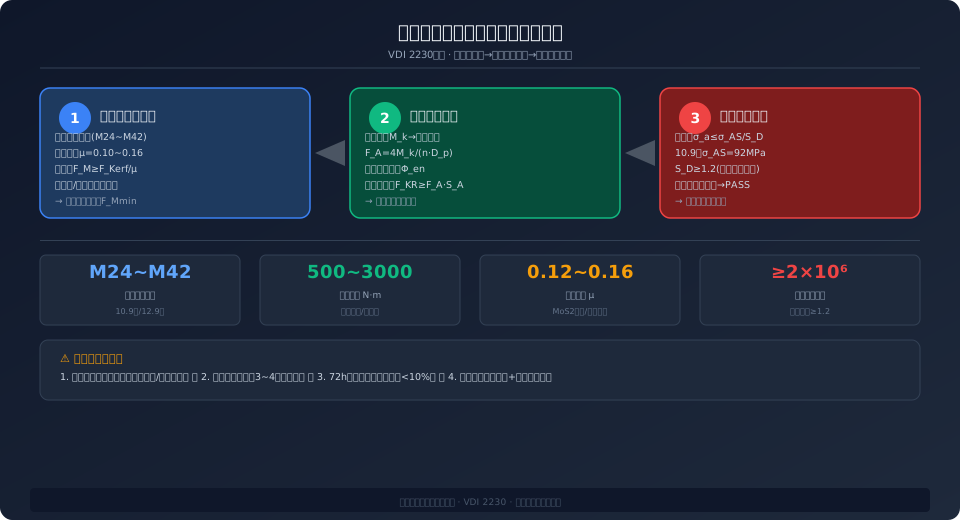
The slewing bearing is the critical component connecting the base to the slewing platform in a deck crane — it must simultaneously absorb axial forces, radial forces, and overturning moments from the crane lighter and load, while ensuring smooth 360° rotation. The dozens of high-strength bolts securing the slewing bearing to the base and turntable are the most critical link in the entire load path — insufficient preload creates clearance in the slewing bearing under overturning moment, and impact load accelerates raceway wear; excessive preload pushes bolts into yielding when combined with working load, potentially causing delayed fracture.
The three-step bolt preload verification method follows VDI 2230 (calculation of high-strength bolted connections), while the load conditions for slewing bearing selection reference the duty combination requirements for slewing mechanisms specified in ISO 4301.
This article applies the VDI 2230 methodology to a 30t·m deck crane slewing bearing, presenting the complete bolt preload verification calculation process.
Step 1: Minimum Clamping Force — Preventing Joint Separation
The primary function of a bolted connection is to ensure that the mating surfaces between the connected parts (slewing bearing inner ring and base flange, outer ring and turntable flange) do not separate under working load. If the joint separates, the full overturning moment is carried by the tension-side bolts alone (instead of being distributed through the contact pressure at the joint interface), and bolt working stress surges by 3–5 times, leading to rapid fatigue fracture.
The minimum clamping force F_Kerf is calculated as: F_Kerf = M_T / (n × r_eff), where M_T is the overturning moment, n is the number of tension-side bolts (typically taken as one-third of the total bolt count, i.e., the one-third arc segment of the bolt circle), and r_eff is the effective radius of the bolt circle. Using a 30t·m deck crane as an example: maximum overturning moment M_T = 680 kN·m (including dynamic load factor of 1.3), slewing bearing bolt circle diameter D = 1200 mm, r_eff = D/2 = 600 mm, total bolt count n_total = 36, tension-side n = 12. Calculation: F_Kerf = 680/(12 × 0.6) = 94.4 kN. Each tension-side bolt must therefore provide at least 94.4 kN of clamping force to maintain joint integrity.
To account for joint surface roughness variations, load estimation errors, and long-term creep relaxation, a safety factor of S_A = 1.4 is applied (per VDI 2230, for slewing bearing connections subject to overturning moment, S_A ≥ 1.3). The design minimum clamping force is therefore F_M_min = F_Kerf × S_A = 94.4 × 1.4 ≈ 132 kN.
Step 2: Working Load Distribution — Additional Bolt Tension
Once preload is applied, the bolt and the connected parts form an elastic parallel system. When an external overturning moment acts on the slewing bearing, the additional axial tensile force F_SA on the tension-side bolts is not equal to the total tensile force generated by the overturning moment. Instead, it is distributed proportionally between the bolt's elastic stiffness and the connected parts' elastic stiffness — this is the load factor Φ concept in VDI 2230.
The load factor Φ = δ_P / (δ_S + δ_P), where δ_S is the elastic compliance of the bolt (mm/N) and δ_P is the elastic compliance of the connected parts. For an M30 high-strength bolt (grade 10.9): bolt compliance δ_S = (L_1/A_1 + L_2/A_2 + ...)/E, calculated segmentally based on each section's length and cross-sectional area. For a standard M30 × 200 mm bolt, δ_S ≈ 2.5 × 10⁻⁶ mm/N. The connected parts' compliance δ_P is calculated using the VDI 2230 deformation cone model: the cone half-angle φ is typically 30°–45° (30° for steel-to-steel joints). For a 30 mm thick slewing bearing race ring plus flange, δ_P ≈ 0.8 × 10⁻⁶ mm/N. The load factor is therefore Φ = 0.8/(2.5 + 0.8) ≈ 0.24 — meaning only 24% of the external axial load is transmitted to the bolt as additional load, while the remaining 76% is balanced by reducing the joint interface pressure. This is the core advantage of bolted connection design: the fatigue load on the bolt itself is far smaller than the external load, resulting in an exceptionally long fatigue life.
The maximum total bolt tensile force F_S_max = F_M + Φ × F_A, where F_M is the assembly preload (taken as the design minimum clamping force of 132 kN × preload coefficient α_A = 1.6 ≈ 211 kN; α_A accounts for friction coefficient scatter and tightening tool accuracy), and F_A is the external axial load (under M_T = 680 kN·m, the outermost tension-side bolt experiences an axial force F_A = M_T × r_max/Σr², where r_max = 600 mm and Σr² ≈ 36 × 0.6² × uniform distribution coefficient = 12.96 m², giving F_A = 680 × 0.6/12.96 ≈ 31.5 kN). Therefore, F_S_max = 211 + 0.24 × 31.5 ≈ 219 kN.
Step 3: Fatigue Strength Verification — Surviving Millions of Cycles
The bolts in a deck crane slewing bearing experience typical pulsating fatigue load — maximum bolt load occurs during full-capacity lifting operations, while minimum load occurs during idle rotation (close to preload). The fatigue stress amplitude σ_a = (F_S_max − F_M) / (2 × A_S) = 0.24 × 31.5 × 10³/(2 × 561) ≈ 6.7 MPa, where A_S = 561 mm² is the stress cross-sectional area of the M30 bolt.
Per VDI 2230, a grade 10.9 M30 bolt with rolled threads after heat treatment (rolled after heat treatment is superior to rolled before heat treatment) has a fatigue limit stress amplitude σ_ASV of 50–60 MPa (depending on surface condition and thread manufacturing process). The safety factor S_D = σ_ASV/σ_a = 55/6.7 ≈ 8.2 — far above the S_D ≥ 1.2 required by VDI 2230, indicating that this bolted connection has an extremely high fatigue safety margin under normal operating conditions.
However, a critical caveat applies: the above calculations assume "assembly preload is precisely controlled to the design value." In real-world service, if maintenance personnel tighten bolts with a manual wrench (achieving only 50%–70% of the design preload), or if corrosion in the marine environment alters thread friction coefficients, the actual preload will deviate significantly from the design value — this is the most common cause of fatigue failure in slewing bearing bolts. Therefore, precise preload control (using hydraulic tensioners or ultrasonic bolt load measurement) is more critical than the bolt strength grade selection itself.
| Design Parameter | Symbol | Value | Basis |
|---|---|---|---|
| Maximumoverturning moment | M_T | 680 k N·m | Includingdynamic load factor1.3 |
| Bolt Specification | M30×200 | 10.9Class | ISO Class 8 (cleanroom)98-1 |
| Bolt Total Number/Tension Side | n_total/n | 36/12Pieces | Bolt Circle D=1200mm |
| minimum Clamping Force | F_M_min | 132 k N | S_A=1.4 |
| Assembly Preload | F_M | 211 k N | α_A=1.6 |
| Load Factor | Φ | 0.24 | δ_S=2.5, δ_P=0.8 |
| Total Working Tension | F_S_max | 219 k N | F_A=31.5kN |
| Fatigue Stress Amplitude | σ_a | 6.7 MPa | A_S=561mm² |
| Fatigue Endurance Stress Amplitude | σ_ASV | 55 MPa | VDI 2230 10.9Class |
| Fatigue Safety factor | S_D | 8.2 | Requirement≥1.2 |
| Bolt Tightening Method | Preload Accuracy | Application Scenarios | Cost |
|---|---|---|---|
| Torque Wrench | ±25% | General Connection, Non-Critical | Low |
| Hydraulic Tensioner | ±10% | Slewing Bearing Critical Bolt | Medium(Per Bolt¥50~150) |
| Ultrasonic Bolt Load Measurement | ±5% | High Accuracy Requirement, Online Measurable | High(Equipment¥5~15Ten Thousand) |
| Torque+Turn-of-Nut Method | ±15% | Batch Assembly, Good Quality Control | Low~Medium |
| Hydraulic Nut | ±8% | Large-Sized Bolt(> M48) | High |
Bolt Locking and Corrosion Protection for Marine Environments
Slewing bearing bolts in offshore environments face two additional challenges: vibration-induced loosening and galvanic corrosion. Hull vibration (10–200 Hz) combined with the micro-motion of slewing rotation causes a gradual loss of bolt preload — even with a perfectly executed initial assembly, preload losses of 15%–25% can occur within 6 to 12 months. Countermeasures include: ① using disc spring washers (per DIN 2093) to compensate for preload loss (elastic recovery ≥ 0.5 mm); ② applying Loctite 243 or Loctite 2701 thread-locking adhesive (medium strength, oil- and seawater-resistant, removable); ③ marking alignment lines (paint marks) across the bolt head and nut face for visual inspection of rotational loosening.
Galvanic corrosion occurs when the electrochemical potential difference between the bolt (high-strength alloy steel) and the slewing bearing raceway (typically 42CrMo4 or C45E quenched and tempered steel) is driven by the seawater electrolyte. Although both materials are steel, the different strength grades (Grade 10.9 bolts contain Cr/Mo alloying elements with a more negative potential) can still produce weak galvanic corrosion. Protective measures: apply a Dacromet coating (zinc-aluminum flake layer, salt spray test ≥ 1,000 h without red rust) to the bolt surface, or the superior Geomet coating (chromium-free, environmentally friendly, with better corrosion resistance); apply seawater-resistant grease (e.g., Molykote P-40 or Klüberplex AG 11-462) inside the bolt holes; and apply sealant on the flange mating surfaces to prevent seawater ingress into the bolt holes.
Engineering Constraints in Slewing Bearing Selection and Bolt Layout
Slewing bearing selection depends not only on load capacity calculations but is also closely tied to the bolt layout. The pitch circle diameter of the bolt holes, the number of bolts, and the bolt size are mutually constrained — the bolt hole spacing (pitch) must be ≥ 3d (d = nominal bolt diameter) to provide adequate wrench clearance, while the edge distance from the bolt hole center to the inner and outer ring edges must be ≥ 1.5d to prevent edge tearing. For M30 bolts, the minimum pitch is 90 mm and the minimum edge distance is 45 mm. If the selected bearing's outer ring width cannot accommodate the required number of M30 bolts, the options are to upgrade to an M36 or larger slewing bearing model (with wider inner and outer rings) or switch to Grade 12.9 bolts to reduce the required quantity — both options mean higher cost and longer lead times.
Another frequently overlooked engineering constraint is the installation accessibility of bolts in the inner ring (connecting to the base) and outer ring (connecting to the turntable). Outer ring bolts are typically inserted from above with nuts tightened from below, providing relatively ample working space. Inner ring bolts, however, are surrounded by the bearing raceway and the crane lighter base, leaving extremely confined space (sometimes only 200–300 mm of vertical clearance), making it impossible to insert a standard hydraulic tensioner. The solution is to plan for bolt access during the design phase — by providing oval hand holes in the base flange for tensioner access, or by using ultra-slim tensioners (e.g., the Tentec SX series, with a height of only 85 mm). If installation accessibility is not considered at the design stage, field installation becomes extremely difficult, potentially requiring flange cutting and re-welding — which is unacceptable in class society projects.
Frequently Asked Questions
Q: Why can't a standard torque wrench be used for deck crane slewing bearing bolts? How is the torque value calculated?
A: A standard torque wrench offers only ±25% preload accuracy — meaning that with a target preload of 211 kN, the actual preload could range from 158 to 264 kN, which is far too wide a spread. The relationship between torque T and preload F is T = K × F × d, where K is the nut factor (dependent on thread friction and bearing surface friction coefficients). For M30 bolts lubricated with molybdenum disulfide, K ≈ 0.14–0.18; T = 0.16 × 211 × 0.03 ≈ 1,013 N·m. However, the K value itself can vary by ±15%, meaning that even with precise torque control, preload deviation can still reach ±15%–20%. For this reason, hydraulic tensioners are recommended for critical slewing bearing bolts — they stretch the bolt shank directly, independent of friction coefficients, achieving preload accuracy of ±10%.
Q: Do slewing bearing bolts require periodic re-torquing? How often?
A: Yes. Newly installed slewing bearing bolts must be re-torqued after 50–100 operating hours (preload loss is most significant during the initial period as microscopic surface irregularities on the mating faces are flattened). After that, inspect monthly for the first 6 months of operation (visual check of alignment marks plus ultrasonic verification of preload on a 10% sample of bolts), then quarterly from months 7–12, and semi-annually after the first year. If two consecutive inspections show no significant preload drop (<5%), the interval can be extended to once a year. When re-torquing, never simply tighten further — first loosen the bolt by a quarter turn, then re-tighten to the target value to eliminate false torque readings caused by thread galling.
Q: How do you replace a broken slewing bearing bolt? Can it be done on an offshore platform?
A: If a single bolt fractures in the threaded section (not at the head fillet radius) and the remaining bolts maintain proper preload with no abnormal noise from the slewing bearing, replacement can be performed without stopping operations (subject to surveyor witnessing). Procedure: ① Use a hydraulic tensioner to release preload on the two adjacent bolts (relieving joint-face pressure at the fractured bolt location); ② Extract the broken bolt (if it sheared inside the tapped hole, use a stud extractor); ③ Inspect the tapped hole for damage (thread gauge + borescope); ④ Install a new bolt with thread-locking compound applied; ⑤ Re-apply preload to the new bolt and adjacent bolts. If more than 10% of the bolts (4 or more) have fractured, this indicates a systemic issue with the design preload or tightening procedure, requiring a shutdown for comprehensive preload verification and bolt material analysis.
Q: Should a deck crane slewing bearing use a three-row roller or single-row four-point contact ball design? Does it relate to bolt preload?
A: The three-row roller slewing bearing (upper and lower rows carry axial loads, radial row carries radial loads) offers higher load capacity and greater stiffness but has a larger overall height and higher cost. It suits large deck cranes with overturning moments exceeding 1,000 kN·m. The single-row four-point contact ball design is compact with lower friction resistance, making it ideal for medium and small deck cranes with overturning moments below 500 kN·m. Regarding bolt preload, the three-row roller type demands higher joint-face stiffness (its thinner inner and outer rings are more sensitive to local deformation), so preload typically follows VDI 2230 recommendations at 1.1–1.2 times the calculated value. The single-row ball type tolerates slightly more joint-face clearance. Both designs require Class 10.9 or 12.9 high-strength bolts — Class 8.8 is not an acceptable substitute.
Kelude Heavy Industry provides full-process technical support for deck crane slewing bearings, from selection calculations and bolt preload verification to on-site installation guidance. Contact our engineering team for a tailored solution.
