

ATEX vs IECEx: Offshore Platform Crane Explosion Protection
Explosion-proof design for offshore platform cranes involves two major certification systems: ATEX (EU) and IECEx (international). Hazardous areas are classified into Zone 0/1/2 (gas) and Zone 20/21/22 (dust). Explosion-proof equipment must be selected according to the area grade, with protection types such as Ex d (flameproof), Ex e (increased safety), or Ex p (pressurized enclosure). Pressurized enclosure is the optimal solution for the electrical control system of large cranes.
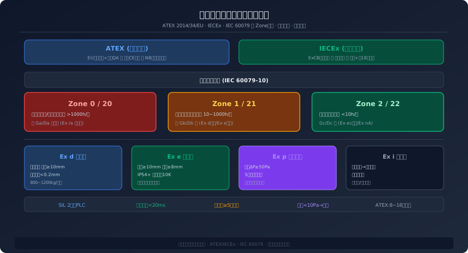
Offshore oil and gas platforms rank among the harshest industrial environments on earth for crane explosion-proof requirements. The drilling area, oil and gas processing area, and wellhead area are saturated with flammable gases such as methane, propane, and hydrogen sulfide. A single spark from any electrical device can trigger a catastrophic explosion—the investigation report on the 1988 Piper Alpha platform disaster in the North Sea (167 fatalities) explicitly identified explosion-proof design defects as a critical link in the accident chain. Explosion-proof design for offshore platform cranes must simultaneously achieve two objectives: preventing electrical equipment from igniting the surrounding explosive gas atmosphere, and maintaining safe operation during crash back scenarios after a leak has occurred to enable personnel evacuation and emergency shutdown.
The discussion of hazardous area classification and equipment selection is based on the IEC 60079 series of standards and the ATEX 2014/34/EU Directive. The structural design of the crane itself follows the safety requirements of ISO 4301 Crane Design Standard.
ATEX vs IECEx: A Full Comparison of Explosion-Proof Certification Systems
ATEX (ATmosphères EXplosibles) is the EU explosion-proof directive (Directive 2014/34/EU), mandatory across the European Union and regions that recognize CE Certification. IECEx (IEC System for Certification to Standards Relating to Equipment for Use in Explosive Atmospheres) is the International Electrotechnical Commission's global explosion-proof certification system, widely adopted outside the EU—including Asia-Pacific, the Middle East, and South America. The technical standards underlying both systems (the IEC 60079 series) have largely converged; the key differences lie in certification procedures and market supervision approaches.
| Certification Dimension | ATEX(EU) | IECEx(International) |
|---|---|---|
| Legal Status | EU Directive, Mandatory | International Standard, Contractual Agreement |
| Applicable Region | EU/EEA/CEMutual Recognition Countries | Global(Asia-Pacific/Middle East/South America) |
| Technical Bid Standard | EN 60079Series(Equivalent IEC) | IEC 60079Series |
| Certification Mode | EU Type Inspection+Factory Quality Assurance | Type Inspection+Factory Quality Assurance+Per Unit Inspection |
| Certification Body | EUnotified body(NB) | IECEx certification Body(Ex CB) |
| Certificate Mutual Recognition | IECEx Certificate Non-substitutable ATEX | ATEXCertificate Partially Accepted |
| Equipment Marking | Ex II 2G Ex db IIB T4 Gb | Ex db IIB T4 Gb |
| Quality Assurance Audit | notified body Annual Audit | Ex CBPer18Monthly Audit |
Hazardous Area Classification – Zone 0/1/2 and Zone 20/21/22
Offshore platforms are classified into hazardous areas in accordance with IEC 60079-10-1 (gas) and IEC 60079-10-2 (dust) standards. Gas environments are divided into Zone 0 (explosive atmosphere present continuously, >1,000 h/year), Zone 1 (likely to occur in normal operation, 10–1,000 h/year), and Zone 2 (not likely to occur in normal operation or only for short periods, <10 h/year). The working areas of offshore platform cranes are typically classified as Zone 1 or Zone 2 — the wellhead and drilling areas are Zone 1 (requiring Ex db or Ex eb protection), while accommodation and utility areas are Zone 2 (where Ex ec protection may be used).
The key basis for Zone 1/2 classification is leak source analysis (Gas Dispersion Analysis) — CFD (Computational Fluid Dynamics) software such as FLACS or KFX is used to simulate the dispersion of flammable gas released from potential leak sources (flanges, valves, sampling points), combined with statistical wind speed and direction data, to determine the probability and duration of an explosive atmosphere in each area. Offshore platform cranes are typically installed at the platform edge (>10 m from leak sources) and on the upwind side; CFD analysis can demonstrate that the crane's working area is Zone 2 — this significantly reduces the explosion-proof cost of electrical equipment (Zone 2 permits Ex ec increased-safety devices, which cost approximately 40%–60% of Ex db flameproof equipment required for Zone 1).
Explosion-Proof Solutions for Crane Electrical Control Systems – Three Protection Types Compared
①Flameproof Ex d — Electrical components are enclosed in a heavy flameproof housing (typically cast iron or cast steel, wall thickness ≥10 mm) that can withstand an internal explosion without damage. The flame path (flange gap <0.2 mm, width ≥13 mm) cools escaping flames so they cannot ignite the external atmosphere. Advantages: no external purge gas supply required, simple maintenance. Disadvantages: heavy enclosure (an Ex d housing for a 200 kW VFD can weigh 800–1,200 kg), poor heat dissipation (requires derating of 30%–50%), and high cost (approximately 3–5 times that of standard equipment). Suitable for small control boxes and sensors.
②Increased Safety Ex e — Enhanced insulation distances (creepage distance ≥10 mm, clearance ≥8 mm), a higher protection rating (≥IP54), and limited temperature rise (10 K lower than standard equipment) ensure that no sparks or excessive temperatures are produced during normal operation. Advantages: lower cost (approximately 60%–70% of Ex d), lighter weight, and better heat dissipation. Disadvantages: only suitable for equipment that does not produce sparks in normal operation (e.g., junction boxes, terminal blocks, squirrel-cage motors); not suitable for VFDs, PLCs, contactors, or other devices with switching elements. Zone 1 requires Ex eb (high reliability); Zone 2 permits Ex ec.
③Pressurized Ex p — A sealed control cabinet is continuously purged with clean protective gas (compressed air or inert gas), maintaining an internal pressure at least 50 Pa above the external atmosphere to prevent explosive gas from entering the cabinet. The protective gas must be filtered (removing oil mist and particulates to ISO 8573-1 Class 2), dried (dew point at least 10°C below ambient temperature), and flow-monitored. The key advantage of the Ex p approach is that any standard industrial electrical equipment (VFDs, PLCs, HMIs, relays, etc.) can be installed inside the cabinet without individual explosion-proof certification — the cabinet itself serves as the explosion-proof enclosure. This makes it the optimal solution for large crane electrical control systems (total power >100 kW, more than 5 control cabinets). Another engineering advantage of the Ex p approach is maintenance convenience — when servicing equipment inside the cabinet (e.g., replacing VFD power modules or troubleshooting PLC faults), maintenance personnel do not need to remove heavy Ex d flameproof covers (a single cover plate can weigh 50–80 kg and require 2–3 people). Instead, they simply press the "Maintenance Mode" button on the HMI — the system automatically executes a standardized purge-and-depressurize sequence to unlock the cabinet door, taking approximately 3–5 minutes in total, and a single technician can open the door within 30 seconds. This is especially important in the high-salinity, high-humidity offshore platform environment, where an Ex d flameproof joint exposed to air must be reassembled within 30 minutes — otherwise salt spray deposits may compromise the flameproof gap. The Ex p solution improves both maintenance efficiency and safety by several times over.
Engineering Design Essentials for Pressurized Enclosure Systems
The core of Ex p pressurized system design is the "five-stage safety logic" — ①Pre-purge stage: Before electrical equipment is energized, the cabinet is purged with protective gas at a flow rate of ≥5 times the cabinet volume (duration calculated as total cabinet volume ÷ purge flow rate, with at least 5 air changes), diluting any residual flammable gas inside the cabinet to below 25% of the LEL (Lower Explosive Limit). Purge flow and pressure are monitored by an orifice flow meter and differential pressure transmitter, with data fed into a safety PLC. ②Pressurization stage: After purging is complete, the inlet valve is adjusted to reduce flow to a maintenance level (approximately 1–2 times the cabinet leakage rate), maintaining internal pressure in the 50–200 Pa range. ③Normal operation stage: The differential pressure transmitter continuously monitors the pressure differential between the cabinet interior and exterior. A drop below 25 Pa triggers an alarm (indicating a door seal or supply line issue); a drop below 10 Pa automatically disconnects the cabinet's main power after a 3-second delay — this is the final line of defense for explosion safety. ④Pressure relief protection: An explosion-proof pressure relief valve (set at 300–500 Pa) is installed on the cabinet top to prevent overpressure from damaging the door seals in the event of a supply system fault. ⑤Emergency shutdown: When the platform ESD (Emergency Shutdown) system is triggered, the Ex p controller receives a dry contact signal and immediately disconnects cabinet power and closes the inlet solenoid valve (isolating the cabinet interior from the external explosive atmosphere).
| Ex p System Component | Technical Requirements | Brand/Model Reference |
|---|---|---|
| Shielding Gas Source | Compressed Air ISO Class 8 (cleanroom)573-1 Class 2 | Platform Shared or Dedicated Airair compressor 7~10bar |
| Filter Regulator Unit | 5μm Pre-filter+0.01μm Fine Filter+Activated Carbon | SMC AFSeries / Norgren Olympian |
| Orifice Flow Meter | Measuring Range0~500L/min ±2%FS | Kobold DON / Endress+Hauser |
| Differential Pressure Transmitter | Measuring Range0~500Pa ±1Pa | Setra 264 / Dwyer 616KD |
| Safety PLC | SIL 2, Scan Cycle<20ms | HIMA HIMax / Siemens S7-1500F |
| Explosion-proof Pressure Relief Valve | Setting300Pa, Flow Rate≥2×Air Supply | Fike / Elfab Customized |
Cable Glands & Wiring: The Most Overlooked Link in the Explosion-Proof Chain
In the explosion-proof design of offshore platform cranes, cable selection and wiring methods are frequently underestimated—yet statistics indicate that roughly 35% of explosion-proof failures stem from improper installation of cable entry devices (cable glands). All cables entering Ex d or Ex e enclosures must pass through certified explosion-proof cable entry devices (Ex d requires flameproof joint compliance with EN 60079-1; Ex e requires sealing per EN 60079-7). The tolerance between the cable outer diameter and the seal ring inner diameter of the entry device must be precisely matched—too loose compromises the seal, while too tight damages the cable sheath. For armored cables, the armor layer must be reliably grounded at the entry device (grounding resistance <4Ω). For unarmored cables entering an Ex d enclosure, maintain a minimum flameproof length of 3m (the cable length before the terminal block inside the Ex d enclosure).
All cables must be marine-grade, flame-retardant, low-smoke, halogen-free (FR-LSZH, per IEC 60092-359), rated at 0.6/1kV, with an operating temperature range of -40°C to +90°C, and must pass the IEC 60332-3-22 bunched flame test. For cables running from the VFD to the motor, a symmetrical shielded construction (3+3 cores, shield coverage ≥85%) is required to suppress high-frequency harmonic electromagnetic radiation and prevent interference with platform communication systems.
Furthermore, close attention must be paid to the distinction between Component Certification and System Certification for explosion-proof equipment. A crane is a system comprising dozens of explosion-proof electrical components (motors, VFDs, sensors, junction boxes, lighting, alarms). Merely holding ATEX/IECEx certificates for individual components is insufficient—classification society surveyors will require a Declaration of Conformity for the complete crane system, issued by a notified body, proving that the interconnections between components (cables, entry devices, Equipotential Bonding) also meet explosion-proof requirements.
Frequently Asked Questions
Q: Is the explosion protection class for an offshore platform crane Zone 1 or Zone 2? Who determines this?
A: This is determined by the project's Hazardous Area Classification Drawing. This drawing is produced by the project's designated safety engineering consultancy (e.g., DNV GL, Lloyd's Register, or Bureau Veritas) based on CFD gas dispersion analysis, and it becomes the design basis after approval by the platform operator and the classification society. Over 90% of offshore platform crane installation locations can be justified as Zone 2. If the CFD analysis cannot adequately rule out Zone 1 (e.g., located <10m from the wellhead area and downwind), the crane must be designed to Zone 1 standards.
Q: Which is more practical on an offshore platform: an Ex p pressurized fume hood or an Ex d flameproof cabinet?
A: For large crane electrical control systems (containing VFDs, PLCs, HMIs, I/O Modules, etc., typically 5-15 Control Cabinets), the Ex p pressurization solution is more practical. It requires only 1-2 large enclosures (welded and sealed from Carbon Steel or Stainless Steel plate) plus a single air supply system, allowing the use of standard industrial components inside. The total cost is typically 40%-60% of a solution using only Ex d flameproof cabinets, and it offers better heat dissipation and easier maintenance (simply depressurize and disconnect power before opening the cabinet door, without removing heavy flameproof covers). For smaller distributed I/O boxes and sensors, Ex d flameproof enclosures are more economical and practical. Recommended approach: use Ex p for the main control cabinet, and Ex d or Ex e for field sensors and junction boxes.
Q: Are ATEX and IECEx certificates mutually recognized? How should I choose if exporting to both the EU and the Middle East?
A: They are not fully interchangeable. An ATEX certificate cannot be legally replaced by IECEx within the EU (an EU Type Examination Certificate is mandatory). However, IECEx is widely accepted in the Middle East (e.g., for ADNOC, Saudi Aramco, QatarEnergy projects), and some clients even mandate it. If your crane is destined for both the EU and the Middle East, obtaining both certifications is recommended. Since the technical standards for both systems are now highly harmonized (both based on the IEC 60079 series), applying for ATEX and IECEx simultaneously takes roughly 12-16 weeks and costs about 30%-40% more than a single certification, which is significantly less than doing them separately.
Q: What happens if the Ex p pressurization system loses its air supply? What is the safety logic?
A: When the differential pressure transmitter detects that the cabinet pressure has dropped below 25 Pa, the safety PLC immediately triggers an audible and visual alarm (with "Cabinet Pressure Loss" displayed on the HMI). The operator then has 15 minutes to investigate and resolve the cause (typical causes include supply line leaks, air compressor shutdown, or improperly sealed cabinet doors). If the pressure continues to fall below 10 Pa, the safety PLC outputs a dry contact signal after a 3-second delay, which trips the main power supply circuit breaker in the cabinet via an undervoltage release coil, while simultaneously closing the supply solenoid valve—at this point, all electrical equipment inside the cabinet is de-energized and the system enters a safe state. This entire process operates independently of external communications or operator intervention; the safety PLC executes autonomously and complies with SIL 2 safety integrity level requirements.
Kelude Heavy Industry offers ATEX/IECEX dual-certification design solutions for offshore platform crane explosion-proof systems, covering hazardous area classification, explosion-proof type selection, and turnkey pressurized ventilation system projects. For detailed technical solutions, please contact our engineering team.
