

Portal Crane Rail Installation Accuracy Control for Shipyard
Portal cranes in shipyards operate on reinforced concrete rails that can stretch for hundreds of meters. The load-bearing capacity of the rail foundation, its settlement control, and installation accuracy directly determine the crane's operational safety and service life. Rail span deviation must be held within ±5 mm, joint gaps between 2–3 mm, and overall elevation deviation ≤10 mm — a full order of magnitude tighter than typical industrial factory crane rail tolerances.
Shipyard portal cranes are the backbone lifting equipment for shipbuilding and repair, with typical lifting capacities of 50–900 t, spans of 50–200 m, and dead weights reaching 1,500–5,000 t. When this "behemoth" travels along its rails, the entire dead weight and lifting load is transferred through 8–16 sets of travel wheels down through the rail, rail clamps, steel base plates, secondary grouting layer, reinforced concrete foundation beams, and into the pile foundation. Any deviation beyond tolerance at any point along this load path can — over years of service — trigger rail crushing, foundation cracking, or even crane overturning.
The load-bearing capacity calculation and installation accuracy requirements for the rail foundation are primarily governed by GB 50278-2010 Code for Construction and Acceptance of Lifting Equipment Installation Works, while crane load values follow the provisions of ISO 4301.
Shipyard crane rail foundations differ fundamentally from the crane runway girders found in ordinary industrial plants. Shipyard portal cranes operate outdoors — exposed to sun, rain, and marine salt spray — with rail runs extending 200–500 m (a single-rail line can serve as the backbone of a 10,000-tonne slipway). The foundation sits directly on soft coastal soil (posing significant settlement risk), and lifting loads feature large eccentricities (hoisting large hull blocks generates substantial overturning moments). These factors together demand far more stringent rail foundation design than conventional industrial applications.
Foundation Structure Types: Portal Frame vs. Pile Cap
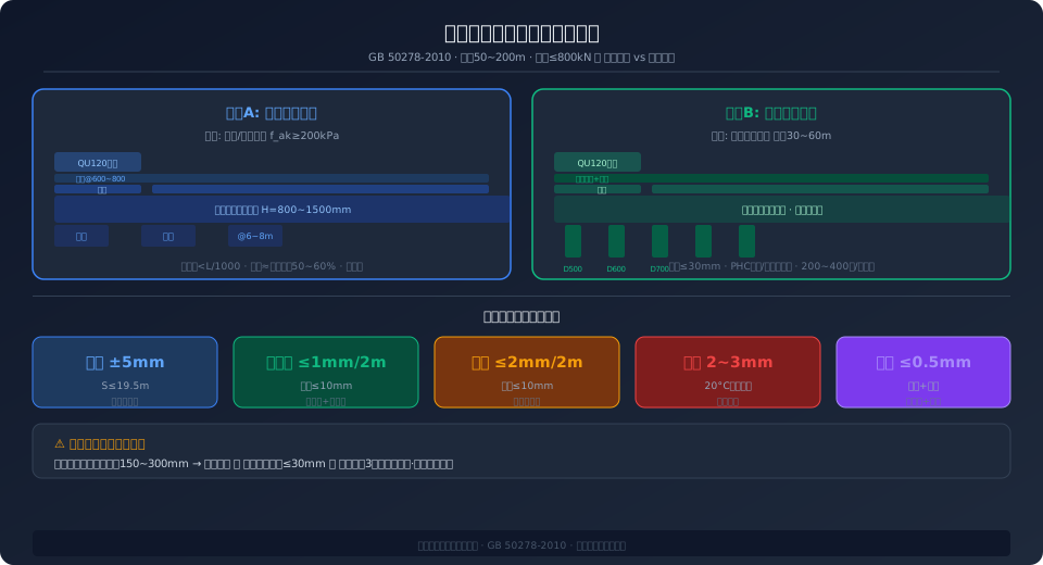
Shipyard portal crane foundations typically use one of two structural configurations. The first is a portal frame foundation (suitable for sites with competent rock or stiff clay): two rows of reinforced concrete columns supporting a continuous top runway beam, with column spacing of 6–8 m and beam section depths of 800–1,500 mm (depending on wheel load and span). Columns transfer loads to the ground through isolated or combined footings. This approach offers faster construction and lower cost (roughly 50–60% of a pile foundation solution), but requires a characteristic subgrade bearing capacity of fak ≥ 200 kPa and settlement differences limited to L/1000 (where L is the column spacing).
The second configuration is a pile cap foundation (the practical choice for soft coastal soils — the reality at most shipyards): PHC spun concrete piles (500–800 mm diameter, 30–60 m long, driven through soft layers to bearing strata) or bored cast-in-place piles (800–1,200 mm diameter), with pile caps tied together to form a continuous rail foundation beam. The initial investment is higher (individual piles run ¥30,000–80,000, and a full rail line may require 200–400 piles), but this approach effectively controls long-term settlement in soft ground — pile foundation settlement typically stays ≤30 mm, whereas un-piled strip foundations can settle 150–300 mm (unacceptable for rail installation accuracy).
Rail Selection: QU Series, A Series, or Welded Rail
The rail cross-sections used for shipyard portal cranes are far heavier than those in ordinary industrial plants. Three rail types are commonly specified:
QU series crane rails (QU70/QU80/QU100/QU120) are the most widely used choice — QU120 features a 120 mm head width, 170 mm rail height, theoretical weight of 118.10 kg/m, and is made of U71Mn steel (tensile strength ≥880 MPa), capable of handling maximum wheel loads of approximately 600–800 kN (depending on wheel diameter and tread hardness). The QU series advantage lies in its optimized cross-section (uniform contact stress distribution between the head radius and wheel tread) and its status as a mature, standardized product.
A series square steel rails (A100/A120/A150) are specified for ultra-large portal cranes with wheel loads ≥800 kN. The A150 square rail measures 150 × 150 mm, is made of 45# steel or hardened 42CrMo (HB280–320), and its top surface is machined by milling to ensure flatness. Square rail contact stress distribution is less favorable than the QU series' curved head profile, but it offers higher load capacity for extreme wheel loads and simplifies elevation adjustment through multi-layer base plates.
Welded rails (e.g., UIC60 railway rails joined by welding) are only suitable for temporary slipways or medium-to-small portal cranes with wheel loads below 300 kN. The contact geometry mismatch (railway wheel flange profiles are incompatible with crane wheels) accelerates wheel flange wear during long-term operation.
Rail Installation Accuracy: Five Millimeter-Level Control Indicators
① Rail span deviation — The allowable deviation in the distance between the two rail centerlines per GB 50278-2010 is ±5 mm (for span S ≤ 19.5 m) or ±[5 + 0.2 × (S − 19.5)] mm (for S > 19.5 m). Shipyard portal crane spans typically range 50–200 m, which by formula yields allowable deviations of approximately ±11 to ±41 mm. In practice, however, stricter internal standards (±5–8 mm) are applied, because synchronization errors between the two outrigger legs during heavy block lifts amplify the effect of span deviation.
② Rail straightness — Lateral deviation within each 2 m inspection segment must be ≤1 mm, with total deviation across the full rail run ≤10 mm. A total station (e.g., Leica TS60, angular accuracy 0.5″) captures rail centerline coordinates every 2 m, and the data is imported into CAD software to generate a deviation curve chart.
③ Rail elevation — Elevation difference between adjacent check points every 2 m along the rail must be ≤2 mm, with the overall difference between the highest and lowest points across the full run ≤10 mm. An electronic level instrument (e.g., Trimble DiNi 03, elevation accuracy ±0.3 mm/km) is used for point-by-point measurement. Stable reference benchmarks (settlement observation stakes) must be established at both rail ends before surveying. At rail joints, the vertical step must be ≤0.5 mm; if misalignment reaches ≥0.3 mm, a surface grinder must be used to dress a smooth transition.
④ Rail joint gap — At 20°C ambient temperature, the joint gap should be held at 2–3 mm (reserving space for thermal expansion). Calculation formula: Gap = α × L × ΔT + 2 mm (installation allowance), where α = 12 × 10⁻⁶/°C (coefficient of thermal expansion for steel), L is the individual rail segment length (typically 6–12 m), and ΔT is the difference between the local extreme maximum temperature and the installation temperature. Example: for L = 12 m and ΔT = 40°C, Gap = 12 × 10⁻⁶ × 12,000 × 40 + 2 ≈ 7.8 mm — this calculated value must be clearly noted in the design documents, with field execution referenced against a table based on installation season and daily temperature.
⑤ Rail joint misalignment — At the joint between two adjacent rails, lateral offset of the rail head sides must be ≤1 mm, and vertical step between rail top surfaces ≤0.5 mm. Measurement is performed with a straightedge and feeler gauge; where limits are exceeded, an angle grinder dresses a smooth transition (transition length ≥50 mm, slope ≤1:100). For welded rail joints (e.g., aluminothermic or flash butt welding), this issue does not arise — but welded rails lose their thermal expansion gap, so the design must incorporate temperature force relief segments (typically a telescoping joint every 100–150 m).
| installation accuracy Item | Standard Value | Detection Tool | Detection Frequency |
|---|---|---|---|
| Crane Rail Span | ±5mm (S≤19.5m) | total station+steel coil Ruler | Per6mPoint |
| Crane Rail Straightness | ≤1mm/2m, ≤10mm/Full Rail | total station+Wire Tension Line | Per2mPoint |
| Rail Elevation | ≤2mm/2m, ≤10mm/Full Rail | Electronic Level Instrument | Per2mPoint |
| Joint Gap | 2~3mm (20°C) | Feeler Gauge | Each Joint |
| Joint Misalignment | ≤0.5mm(Height)/≤1mm(Side) | Straightedge+Feeler Gauge | Each Joint |
| Rail Base and Base plate Gap | ≤0.2mm (No Feeler Insertion) | 0.2mm Feeler Gauge | Each Piece Base plate |
| Rail Clamp / Rail Clip Type | Tightening Method | Application Wheel load | Pros and Cons | |||
|---|---|---|---|---|---|---|
| Welding Clamp Plate | Clamp Plate Welding For Base plate | ≤400kN | Fast Installation but Inconvenient Bolted Clamp Plate Clamp Plate | Clamp Plate+Anchor Bolt | ≤600kN | Removable Air Compressorbut Prone to Loosening |
| Hook Type Bolt + Epoxy Grout | Hook Bolt+Grouting Fixing | ≤800kN | High Load Capacity but Installation Accuracy Demanding | |||
| Elasticity Clamp Plate+Anti-Loosening Nut | Disc Spring+Lock Nut | Optional | Compensates Loosening but High Cost |
Managing Long-Term Settlement on Soft Soil Foundations
The most demanding foundation challenge at coastal shipyards is long-term differential settlement of soft soil. Major Chinese shipbuilding hubs—Shanghai, Ningbo, Guangzhou, and Tianjin—typically sit on marine clay and silty clay with a compression modulus (Es) of only 2–5 MPa, compared to over 8 MPa for normally consolidated clay. Under the combined dead weight and service loads of a portal crane, settlement can continue for 5 to 10 years. If differential settlement pushes the elevation difference between the two rails beyond L/800 (e.g., 187 mm for a 150 m span), the crane bridge travel mechanism will experience severe flange rubbing—where the wheel flanges continuously grind against the rail sides—shortening wheel and rail service life to one-fifth or one-third of normal.
Three measures are essential to control settlement. First, pile foundations must penetrate the soft layer and bear on competent strata (bedrock or stiff clay), with pile tips embedded at least two pile diameters into the bearing layer, limiting total settlement to ≤30 mm. Second, use a variable-stiffness leveling design: tighten pile spacing (2–3 diameters) in the central zone where crane loads are highest, and relax it (4–5 diameters) toward the edges, so that pile-soil stress distribution under the foundation slab remains uniform. Third, install settlement monitoring points (stainless steel ball-head benchmarks) along the runway beam every 20–30 m, and run closed leveling loops with an electronic level instrument once per quarter. Plot time-settlement curves and, if the settlement rate exceeds 2 mm/month, initiate ground improvement such as driven steel pipe piles or high-pressure jet grouting.
Grounding and drainage of the rail foundation also deserve close attention. A continuous hot-dip galvanized flat steel ground conductor (40×4 mm) must run the full length of the crane rail, welded to the foundation rebar mesh every 30 m, with a grounding resistance of ≤4 Ω. This conductor serves both the current collector ground brush on the bridge travel mechanism and the lightning protection system. For drainage, install 300 mm wide × 200 mm deep concrete trenches on both sides of the rail foundation, sloped at ≥0.5% toward collection wells, to prevent rainwater and seawater from pooling and accelerating concrete carbonation and rebar corrosion.
Frequently Asked Questions
Q: How often should shipyard portal crane rails be inspected, and what checks are performed?
A: Per FEM 1.001 and ISO 12480 requirements for crane rail installation and acceptance, a full initial survey must be completed after installation, covering five key indicators: span, straightness, elevation, joint gap, and joint offset. During the first year of operation, inspect quarterly (the active settlement period); in year two, switch to semi-annual inspections; from year three onward, annual inspections suffice. Schedule each survey under similar temperature conditions (early morning or overcast days to avoid solar-induced thermal distortion), and position the crane away from the surveyed section so wheel loads do not skew elevation readings. Keep all inspection reports on file until the crane is decommissioned—they serve as compliance documentation for shipyard equipment management.
Q: What should we do when rail joint gaps close up in winter or exceed limits in summer?
A: This is the classic thermal expansion problem. In winter, when rail temperature drops below the installation temperature, gaps can close completely, causing end-to-end contact that leads to rail end crushing and deformation. The solution starts at installation: follow the design's temperature-to-gap correlation table rather than a fixed rule like "3 mm at 20°C." If installing on a 35°C summer day, set gaps at 1.5–2 mm; on a 5°C winter day, use 5–6 mm. If gaps have already closed up, cut 2–3 mm off the rail ends with a rail cutter during the coldest part of the night and re-dress the joints. For long-term reliability on rails longer than 150 m, install expansion joints (e.g., General Track Expansion Joint) in the middle of the run, using spring or hydraulic dampers to absorb thermal movement.
Q: What grout should be used under rail base plates? Is standard C30 concrete acceptable?
A: No, standard C30 concrete is not acceptable. The secondary grout layer beneath the rail base plates is subjected to repeated impact and vibration from wheel loads, and ordinary concrete will crack and debond under cyclic loading. You must use a non-shrink grout with a 28-day compressive strength of ≥60 MPa (vs. 30 MPa for C30), a 1-day strength of ≥25 MPa for rapid return to service, a flowability of ≥290 mm to self-level into the tight gap between the base plate and the runway beam, and a slight volumetric expansion after hardening (+0.1% to +0.3%) to prevent shrinkage gaps. Recommended products include SikaGrout-318, BASF MasterFlow 9500, or the H-40 series. Before grouting, roughen, clean, and pre-wet the substrate to a saturated surface-dry condition, and wet-cure for at least 7 days after placement.
Q: Can a shipyard portal crane share its rail with other cranes?
A: Not recommended. The design wheel load for each crane rail is calculated based on the maximum wheel load of a specific crane model plus the dynamic load factor. If two cranes with significantly different wheel loads are operated on the same rail, the wheel load of the heavier crane may exceed the design load capacity of the rail intended for the lighter crane—particularly risking crushing of the base plate and grout layer. If sharing the rail is unavoidable, the foundation bearing capacity must be re-verified and reinforced to the parameters of the heavier crane. This typically means upgrading the crane rail specification by one step (e.g., from QU80 to QU100), reducing base plate spacing (from 800mm to 500mm), and adding pile foundations. After reinforcement, the full rail accuracy must be re-measured and re-adjusted.
Kelude Heavy Industry provides complete engineering services for shipyard portal crane rail foundations—from geotechnical investigation and foundation design to rail installation and precision alignment. Contact our engineering team for a tailored solution.
