

Overhead Crane Control Cabinet Integration & Electrical Design
Crane Control Cabinet Integration and Electrical Design: Standardized Power Distribution and Assembly Practices. The crane control cabinet serves as the physical backbone of the crane electrical system—integrating the PLC, VFD, power supply modules, Safety Relays, Terminal Blocks, and cooling system into a standardized enclosure that ensures reliable operation in harsh workshop environments.
The crane control cabinet is the physical carrier of the crane electrical system, housing the PLC, VFD, power supply modules, Safety Relays, Terminal Blocks, and cooling system in a standardized enclosure designed for dependable performance under demanding workshop conditions. Kelude Heavy Industry has developed a standardized crane control cabinet design in accordance with GB/T 7251.1-2020 and IEC 61439 standards, covering enclosure selection, power distribution design, component layout, internal wiring, thermal calculations, and EMC protection. This article provides a comprehensive walkthrough of the engineering process—from electrical design through assembly and commissioning.
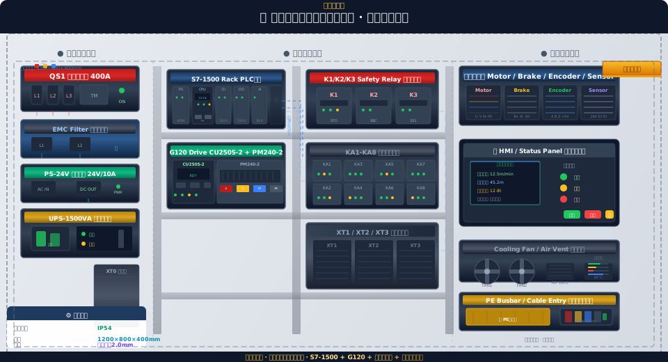
Control Cabinet Design and Protection Rating (IP)
The design of a crane control cabinet begins with enclosure selection and determining the Protection Rating (IP). Kelude Heavy Industry's standardized crane control cabinets are fabricated from Stainless Steel or cold-rolled steel plate (2.0mm thickness), with cabinet dimensions of 1200mm (H) × 800mm (W) × 400mm (D), providing an internal clearance of approximately 0.38 cubic meters. The Protection Rating is selected based on the installation location: cabinets mounted inside the crane operator's cab use IP54 (Dustproof + splash-water resistant), cabinets installed on the workshop floor or on Columns use IP55 (Dustproof + Water Jet Proof), and cabinets deployed in foundry or metallurgical applications use IP65 (Dustproof + hose-down resistant) with an internal positive-pressure ventilation system to prevent Corrosion from aggressive gases. The cabinet door features a three-point locking hinge mechanism, with an EPDM closed-cell sponge rubber Sealing strip rated for -40 to 120°C, providing a service life of no less than 5 years.
The interior is organized into functional zones. The left section (200mm wide) houses the power supply inlet, including the incoming Circuit Breaker, EMC Filter, Switching Power Supply, and UPS. The center section (430mm wide) is the control and drive zone, arranged in two tiers from top to bottom: the S7-1500 PLC rack and G120 VFD on the upper tier, with the Safety Relay group and Intermediate Relay group below. The right section (170mm wide) is dedicated to wiring and output, featuring the outgoing Terminal Block rail and reserved Cable channels. The three zones are physically separated by metal Diaphragms or wire ducts, with Power Cables and signal cables routed on separate levels. The cabinet base is fitted with cable entry points (four 32mm knockouts) and a PE Grounding copper busbar (30mm × 5mm cross-section), while the top provides Cable exit points and a mounting position for the Cooling Fan.
Power Supply System and Distribution Design
The Power Supply system of the crane control cabinet is structured in four stages: incoming protection, filtering, DC power conversion, and backup power. The incoming protection stage uses a 3-pole molded-case Circuit Breaker (rated current 400A, breaking capacity 50kA, Model NSX400F or TM400D). The incoming Power Cable is a YJV-0.6/1kV 4×185+1×95mm² copper-core Power Cable with a current-carrying Capacity of approximately 370A (in free air). The incoming Circuit Breaker is equipped with a thermal-magnetic trip unit—thermal trip set at 400A, magnetic trip set at 3200A (8× rated current)—with a short-circuit interruption time of less than 20ms. This breaker also serves as the main Disconnect Switch for the entire cabinet, with auxiliary contacts wired to the PLC for status monitoring.
The EMC Filter is installed downstream of the incoming Circuit Breaker. A three-phase, three-wire EMC Filter (rated current 400A) provides insertion loss greater than 60dB across the 150kHz–30MHz Frequency range. The Filter's Grounding terminal is connected directly to the PE Grounding copper busbar via a 6mm² yellow-green grounding wire, with a Grounding lead length not exceeding 300mm. VFD Power Cables downstream of the Filter pass through ferrite cores (3 turns) with a 32mm inner diameter to further suppress high-frequency common-mode interference from the drive. The Switching Power Supply is a 24V DC/10A DIN-rail mount unit (input: AC 380V Three-Phase Four-Wire; output: DC 24V/10A, 240W), powering the PLC, HMI, Safety Relays, and Sensors. The input side is protected by a C20 miniature Circuit Breaker (single-pole, C-curve), and the output side is fused with positive and negative rail Fuses (rated current 12A).
| Power Supply Hierarchy | Components | Specification | Protection Configuration |
|---|---|---|---|
| Incoming Line Protection | 3PMolded Case Circuit Breaker QS1 | 400A/50kA | Thermal-Magnetic Trip, Auxiliary Contact |
| Filtering & Conditioning | EMCFilter | 400A/3P | 150kHz~30MHz >60dB |
| DC (Direct Current)Power Supply | Switching Power Supply PS-24V | 24VDC/10A/240W | C20 MCB+12AFuse |
| Backup Power Supply | UPS-1500VA | 1500VA/15min | Automatic Transfer<5ms |
The UPS is installed in the backup power layer with a capacity of 1500VA (approximately 1050W output power), providing about 15 minutes of backup time under a 24V DC load. The UPS input is connected via a miniature circuit breaker to the front end of the switching power supply, while its output feeds the PLC CPU module and HMI. With an automatic transfer time of less than 5ms, the UPS ensures the PLC does not power-cycle during brief external power interruptions. Battery status (on-line discharge / charging / battery low) is communicated to the PLC digital input module through dry contacts. When the UPS battery runs low, the PLC automatically executes a safe shutdown routine and saves operational data.
PLC and VFD Integration in the Control Cabinet
The mounting position and spacing between the S7-1500 PLC and the G120 VFD directly affect heat dissipation and electromagnetic compatibility inside the control cabinet. The PLC rack is installed in the left section of the cabinet's middle area, at an installation height of approximately 400mm from the cabinet floor — a level that allows operators to easily view the LED indicator lights and display screen on the CPU panel. From left to right, the PLC rack accommodates the PS 60W power supply module, CPU 1516-3 PN/DP, DI 32×24V DC module, DO 32×24V DC/0.5A module, and AI 8×U/I module. Adjacent modules are interconnected via U-type bus connectors with zero spacing between modules.
A minimum horizontal clearance of 100mm is maintained between the PLC and the VFD. The VFD selected is the G120 CU250S-2 DP control unit paired with a PM240-2 power module. The control unit is mounted above the PM240-2, connected via a Drive-CLiQ cable. The VFD heat sink fins face forward (toward the cabinet door), allowing hot air to rise and exhaust along the front of the enclosure. A 200mm clearance is reserved below the VFD for output wiring (U/V/W three-phase cables and braking resistor cables). The U/V/W cables must not share the same cable duct as the PLC DI/DO signal cables, and a minimum separation of 200mm is required. The VFD PE grounding terminal is connected directly to the PE grounding copper busbar using a 10mm² yellow-green grounding wire, with a straight-line grounding path not exceeding 500mm.
Wire selection inside the control cabinet follows the IEC 60227 standard. PLC DI/DO signal cables use RVVP 4×0.5mm² shielded cables with the shield grounded at a single point on the PLC side (connected to the PLC grounding rail). Analog signal cables (AI 4~20mA) use RVVP 2×0.75mm² twisted-pair shielded cables with the shield grounded at a single point on the sensor side. PROFINET communication cables are CAT6A S/FTP shielded Ethernet cables fitted with IP20 RJ45 connectors at both ends. These cables run along the left-side cable duct of the cabinet, maintaining a minimum separation of 200mm from power cables. VFD power cables (U/V/W) are YJV-0.6/1kV 3×16mm²+1×10mm² copper-core power cables with an outer diameter of approximately 22mm and a minimum bending radius of 5 times the cable diameter.
Safety Relay and Intermediate Relay Wiring Layout
The safety relay and intermediate relay assembly area is located in the right section of the cabinet's middle area, directly adjacent to the PLC rack. Three Siemens 3SK1121-1AB41 expandable safety relay modules are installed per overhead crane — K1 executes the STO (Safe Torque Off) function via PROFIsafe connection to the VFD, K2 performs the SBC (Safe Brake Control) function independently controlling the double brake electromagnets, and K3 implements the SS1 (Safe Stop 1) function monitoring deceleration and stop time. Each safety relay module is 22.5mm wide and mounted on a DIN rail, with 10mm spacing between modules for heat dissipation and wiring access.
All control logic wiring between the safety relay and the intermediate relays is fully pre-wired at the factory before the crane control cabinet ships. After pre-wiring, the F-LAD logic is verified using the Safety Admin tool in TIA Portal, and the correspondence between PLC DO output points and intermediate relay coils is checked. Both ends of each wire are fitted with heat-shrinkable marker sleeves (printed with the device tag and terminal number, e.g., K1-A1 indicates the K1 relay coil terminal A1). These sleeves are made of PVC heat-shrink tubing (3mm inner diameter, 2:1 shrink ratio) and printed using a label printer such as the Phoenix Contact THERMOMARK ROLL, with a minimum font height of 2mm.
Terminal Blocks & Cable Exit Design
The outgoing terminal blocks in the control cabinet form the interface between the internal wiring and the external equipment cables. Kelude Heavy Industry configures three terminal block groups in the crane control cabinet: XT1 is the power terminal block (mounted on the incoming side for the main power connection), XT2 is the control signal terminal block (mounted in the middle-right section for PLC DI/DO, sensor signals, and communication cables), and XT3 is the motor output terminal block (mounted on the outgoing side for the VFD U/V/W output and brake cables). XT1 terminals are Phoenix Contact PT 35/3-3P (rated current 125A, rated voltage 1000V), XT2 terminals are Phoenix Contact PT 2.5-2P (rated current 24A, rated voltage 800V), and XT3 terminals are Phoenix Contact PT 16-4P (rated current 76A, rated voltage 1000V).
Terminal block identification follows a clear standard. A marker bracket is installed at the start of each terminal block, holding a label that prints the terminal block name and number range, such as XT2:001-050 (control signal terminal block, terminals 1 to 50). Each individual terminal is marked with its terminal number according to the wire labeling rule—for example, "XT2:023" indicates terminal 23 on the XT2 block. Wiring follows the "top in, bottom out" principle: internal device wires enter from the top of the terminal block, while external equipment cables exit from the bottom.
Cable entry sealing is designed for robustness. The cable entry points at the bottom of the cabinet use a combination of knock-out holes and cable glands (PG29 or PG36 type). These glands have a protection rating of at least IP68, and their inner diameter is matched to the cable outer diameter using reducing seal rings for different wire gauges. Incoming cables are provided with a minimum of 500mm of service loop inside the cabinet and are secured at the entry point (using cable clamps or tie wraps fixed to the mounting plate), with the fixing point no more than 100mm from the entry hole. Three spare knock-out holes are pre-punched for future cable routes and sealed with blanking plates; these spare holes have a diameter of 32mm.
Cooling, EMC, and Commissioning
Effective cooling and EMC protection are critical for the long-term reliability of the electrical equipment. Heat dissipation calculation: The main heat-generating components inside the cabinet are the G120 VFD (approx. 1200W at full load), the switching power supply (approx. 30W), the PLC modules (approx. 20W total), and the intermediate relay group (approx. 15W total). The total heat dissipation is approximately 1265W. Based on the cabinet surface area (approx. 2.6 m²), natural convection cooling capacity is about 200W, leaving a deficit of 1065W that requires forced cooling. Cooling solution: Two axial fans (model SANYO DENKI 9GV1212P1G03, 120mm × 120mm × 38mm, airflow 94 CFM each, noise 45dB(A)) are installed at the top of the cabinet door. Each fan is equipped with a stainless steel guard and filter (10-micron filtration). The fans blow downward (intake), and hot air exits naturally through the exhaust grille at the top.
EMC protection measures. The cabinet body acts as a shield—all doors, side panels, and the top panel are electrically bonded using conductive foam (EMC gasket), with a contact resistance of less than 10mΩ per meter. The VFD power cables (U/V/W) pass through a ferrite core (3 turns) before exiting; the core has a 32mm inner diameter and provides an impedance of at least 200Ω at 30MHz. The PLC DI/DO signal cables are routed through a cable shield clamp before entering the PLC (the shield is clamped and grounded at the grounding point on the PLC mounting rail), with the clamp located no more than 50mm from the PLC module. The point-to-point grounding resistance of the PE copper busbar is less than 0.5Ω. The grounding busbar is connected to the workshop grounding grid via a 16mm² yellow-green grounding cable, with a total grounding resistance of less than 4Ω (compliant with the IEC 62305 lightning protection standard).
Factory commissioning follows a five-step process. Step 1: Insulation test—using a 500V megohmmeter, measure the insulation resistance of incoming lines L1/L2/L3 to PE, which must be greater than 1MΩ; the insulation resistance of DI/DO signal lines to PE must be greater than 5MΩ. Step 2: Power supply test—after closing the main switch, check the incoming voltage (three-phase 380V ±10%), the switching power supply output voltage (24V ±0.5V), and the UPS charging status. Step 3: I/O point-to-point test—using the force function in TIA Portal, test each DI input and DO output point individually. All input points must correctly reflect their signal status on the PLC, and all output points must correctly activate their corresponding relays and indicator lights when forced. Step 4: Communication test—verify that the PLC, VFD, and remote I/O stations are all online in the PROFINET network, and that the OPC UA server can correctly read all 26 standard data nodes. Step 5: Full system burn-in—run the control cabinet with no load for 24 hours, recording the internal temperature every 30 minutes (must not exceed ambient temperature +15K). If a temperature anomaly is detected, check the fan operation and the airflow path for obstructions.
Frequently Asked Questions (FAQ)
Q: Why is the crane control cabinet rated IP54 instead of IP65?
A: IP54 is specified for operator-cab-mounted installations because it offers better heat dissipation than IP65, eliminating the need for a heat exchanger. For harsh environments such as foundries and metallurgical plants, IP65 with positive-pressure ventilation is recommended.
Q: What are the installation requirements when a PLC and VFD share the same cabinet?
A: Maintain a minimum clearance of 100 mm between the PLC and the VFD. Mount the PLC upstream of the airflow. Keep power lines at least 200 mm away from signal cables, route them in separate cable ducts, install ferrite cores on VFD output cables, and use a common PE copper busbar for grounding.
Q: How is the required cooling fan airflow calculated?
A: Use the formula Qf = Q / (ρ × Cp × ΔT). For a crane control cabinet with 1265 W of heat dissipation and a ΔT of 15 K, the required airflow is 148 CFM. The standard configuration uses two 120 mm fans providing a combined 188 CFM.
Q: Where should the EMC filter be installed?
A: Install the EMC filter downstream of the incoming circuit breaker and upstream of all loads. Keep it within 300 mm of the incoming terminals, ensure the ground wire does not exceed 300 mm, and route input and output cables separately.
