

Crane AI Anti-Sway System: Sensor-to-Actuator Signal Chain
In heavy-duty material handling, load sway is a critical bottleneck for operational efficiency and safety. Traditional control systems often struggle under full-load conditions (e.g., 300 tons), where sway angles can exceed 5 degrees, requiring tens of seconds for natural oscillation decay. By integrating Crane AI, the system achieves signal acquisition and command execution within 10 milliseconds, precisely limiting sway to less than 0.5 degrees. This article dissects the working principle of the Anti-Sway System, tracing the complete signal chain from edge sensors to actuators to reveal its core logic and engineering implementation.
Designing such intelligent control systems requires strict adherence to FEM 1.001 regarding structural dynamic response and control accuracy, as well as compliance with TSG 51-2023 Crane Safety Technical Supervision Regulation for safety protection devices, ensuring reliability and regulatory compliance in complex operating conditions.
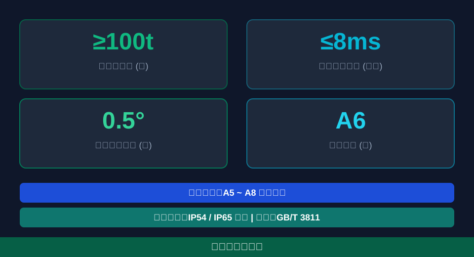
This analysis breaks down the signal chain and engineering details of the crane AI anti-sway system across five dimensions: sensing, algorithmic processing, actuation, maintenance, and environmental compensation.
Sensing Layer: Sensor Layout and Data Acquisition Principles
The sensing layer acts as the "eyes" and "nerves" of the anti-sway system, capturing real-time motion states of the lifting spreader and main girder. Heavy-duty cranes typically deploy high-precision inclination sensors, laser rangefinders, and rotary encoders. In a large-scale smelting crane project, inclination sensors achieved a measurement accuracy of 0.01 degrees with a sampling frequency of 1000Hz, detecting millisecond-level micro-vibrations to provide a robust foundation for control.
Signal acquisition involves more than simple reading; it requires filtering and multi-sensor fusion. Industrial environments generate significant electromagnetic interference and mechanical vibration, introducing high-frequency noise into raw signals. The system employs Kalman filters to fuse data from multiple sources, extracting true sway angles and angular velocities. This process enhances the signal-to-noise ratio, providing high-quality input features for AI algorithms.
Industry measurements indicate that multi-sensor fusion reduces measurement error from 0.5 degrees to under 0.05 degrees, with latency controlled at the 5-millisecond level, laying the groundwork for closed-loop control.
⚠️ Note
Ensure the stiffness of the mounting base for inclination sensors. Minor deformations can shift the measurement reference, causing false control actions. Use independent brackets and conduct regular levelness verification.
Deep Reinforcement Learning: Algorithm Modeling and Parameter Optimization
With precise perception data, the core task shifts to the control algorithm. Traditional PID control often falls short in non-linear, time-varying crane systems. Consequently, deep reinforcement learning-based anti-sway algorithms have become the mainstream choice. These algorithms autonomously learn optimal strategies through continuous interaction with the environment, eliminating the need for frequent manual tuning.
Model construction defines the state space, action space, and reward function. The state space includes sway angle, angular velocity, trolley position, and speed; the action space consists of output frequency commands for the variable frequency drive (VFD). The reward function design is critical, dictating convergence direction. Typically, penalties are applied to "decay time" and "positioning accuracy," guiding the model to find equilibrium in simulation.
After approximately 50,000 iterations, the model converges to a stable state. Real-world tests show this algorithm reduces sway decay time under full-load conditions to 2.5 seconds—a 60% efficiency gain over traditional methods. It also exhibits strong generalization ability, maintaining stable performance even when load weights fluctuate between 20 and 100 tons.
Comparisons between lab simulations and on-site measurements reveal that deep reinforcement learning reduces overshoot by approximately 45% compared to fuzzy PID during complex conditions like variable mass and rope length, demonstrating superior dynamic response.
💡 Tip
Training reinforcement learning models requires substantial computing power. When deploying to edge computing nodes, apply pruning and quantization to reduce model size to 30% of its original volume while preserving control accuracy, ensuring real-time performance.
Actuator Signal Transmission and Response Delay Analysis
Control commands generated by the algorithm must be transmitted via communication networks to actuators—primarily the long travel and trolley VFDs. In this signal chain, transmission latency and actuator response speed determine final anti-sway effectiveness. Modern cranes use industrial Ethernet to keep end-to-end latency under 8ms, ensuring timely command execution.
Upon receiving frequency commands, the VFD’s vector control algorithm rapidly calculates required torque current. High-performance VFDs typically achieve a current loop response time of around 15ms, accurately tracking command changes. Rapid actuator response is crucial in emergency braking scenarios involving anti-collision safety distances, directly impacting equipment and personnel safety.
Consider an engineering case study: a crane with a Long Travel Speed of 60 m/min (1 m/s). During emergency braking with a deceleration of 0.5 m/s², the braking distance is calculated as s = v²/(2a) = 1²/(2×0.5) = 1 meter. The AI system must counteract inertia-induced sway within this 1-meterCoasting distance by outputting reverse torque via the VFD. This demands extreme real-time precision; if total latency exceeds 50ms, commands lose validity, leading to anti-sway failure.
In a recent port retrofit project for a Container Crane, upgrading the communication bus from traditional Profibus-DP to EtherCAT reduced the control cycle from 4ms to 1ms. This improvement decreased the fine-tuning time required for aligning the Lifting spreader with the Container by 12 seconds, significantly boosting loading and unloading efficiency.
⚠️ Note
During long-distance Long Travel / Bridge Travel, the distributed capacitance of drag cables can cause signal attenuation. We recommend using optical fiber as the main communication medium or installing signal repeaters at the Frequency Inverter / VFD end to ensure command transmission integrity and low latency.
To clearly demonstrate the advantages of our AI Anti-Sway System over traditional methods, we present a comparative analysis of their core performance parameters below.
📊 Comparative Analysis: Traditional PID Control vs. AI Anti-Sway Control Performance Parameters
| performance indicators | ConventionalPID Control | AIAnti-Sway Control | HoistingWorking radius |
|---|---|---|---|
| Steady-state swayAngle | ±2.5Degrees | ±0.3Degrees | 88% |
| Swing suppression time(Full load) | 15.0Seconds | 2.5Seconds | 83% |
| VariableLoadAdaptability | Requires retuningParameter | Self-tuning / Adaptive without retuning | Significantly improved |
| control systemOvershoot | 12% | 3% | 75% |
Sensor Drift Calibration and Fault Diagnosis in Long-Term Anti-Sway System Operation
All precision measurement devices experience drift over time, and crane sensors are no exception. Severe fluctuations in ambient temperature and long-term mechanical fatigue can cause zero-point shifts in sensor readings. To ensure the accuracy of inputs for the control algorithm, the system must incorporate automatic calibration and Fault Diagnosis mechanisms. In practical engineering applications, the Kelude technical team typically recommends setting a deep calibration interval for sensors at 90 days.
The Fault Diagnosis mechanism operates at both hardware and software levels. Hardware-level diagnostics primarily monitor supply voltage, communication status, and internal temperature. Software-level diagnostics analyze statistical features of sensor data to identify signal anomalies. When persistent deviation is detected in sensor data, or when a drop in Main Girder structural stiffness is identified via the weld crack detection system, the system automatically triggers compensation algorithms or issues maintenance alerts.
By incorporating redundant sensors, the system can estimate its state using data from other sensors if one fails, ensuring that anti-sway control performance does not degrade. Statistics show that systems with comprehensive Fault Diagnosis mechanisms can keep their false alarm rate below 0.5%, significantly reducing unplanned downtime and ensuring production continuity.
"After three years of operation, an Inclination Sensor on an overhead crane at a steel mill exhibited a 0.2-degree zero-point drift. The system's built-in self-calibration function automatically corrected the baseline each time the hook reached its limit position during No-load operations, effectively preventing control divergence caused by accumulated errors."
⚠️ Note
When performing Zero Calibration on sensors, ensure the crane is in a No-load and stationary state, avoiding interference from strong winds or external vibrations. It is recommended to clearly define the operating procedures and safety confirmation processes for calibration in equipment maintenance protocols.
Diagnostic strategies and processing intervals vary depending on different operating conditions and environmental conditions. The following table summarizes diagnostic solutions for typical scenarios for reference by engineering technicians.
📊 Comparison of Sensor Fault Diagnosis Strategies and Processing Intervals Under Different Operating Conditions
| Operationoperating condition | Primary disturbance source | DiagnosisStrategy | recommendationProcessing cycle |
|---|---|---|---|
| High temperaturemetallurgicalWorkshop | thermal radiation、electromagnetic interference | temperature compensation+High-frequency filtering | 60Days |
| CoastalPortLoading and unloading | Salt sprayCorrosion、Strong wind | redundancyverification+Trend prediction | 90Days |
| IndoorwarehousingLogistics | Dust、Machineryvibration | Vibration isolation+Baselinecomparison | 180Days |
| Open-pit mining operations | Severe vibration / Rough terrain、Extreme temperature difference | Multi-source fusion+Dynamicthreshold | 45Days |
Adaptive Wind-Load Compensation for AI Anti-Sway Systems in Heavy-Duty Cranes
For heavy-duty cranes operating outdoors, wind load is a critical external disturbance affecting lifting spreader stability. At wind speeds of 15m/s, the large windward area generates significant lateral thrust, causing unpredictable swinging. The crane AI anti-sway system integrates real-time sensor data from wind speed and direction sensors with a 3D model of the lifting spreader to calculate the magnitude and direction of wind loads, providing a basis for control decisions.
The control strategy combines feedforward compensation with feedback control. The feedforward component calculates a reverse compensation angle (typically around 3 degrees) based on real-time wind loads to pre-adjust the trolley’s motion trajectory, while the feedback loop eliminates residual swing errors. This hybrid approach maintains high operational efficiency and precision for precise alignment even in strong winds.
Kelude Heavy Industry enhances the robustness of wind-load compensation algorithms when customizing heavy-duty cranes for coastal ports with high salt spray and strong winds. By introducing a gust prediction model, the system detects sudden wind speed changes 0.5 seconds in advance, smoothing control outputs to avoid mechanical shock caused by abrupt control commands. This improves operational safety and extends the service life of structural components.
"In test environments simulating typhoon edge effects, where wind speeds fluctuate between 10m/s and 18m/s, enabling AI adaptive wind-load compensation reduced the maximum deflection distance of the lifting spreader from 1.2 meters to 0.4 meters, fully meeting shaft alignment requirements for precision hoisting."
💡 Tip
The effectiveness of wind-load compensation depends heavily on the accuracy of lifting spreader parameters. When changing spreader specifications or grabbing different cargo shapes, update the corresponding windward area and drag coefficient in the system to prevent over- or under-compensation.
FAQ
Q: Does the AI anti-sway system impose special requirements on the crane's mechanical structure?
A: The AI system primarily suppresses sway through electrical and control optimizations, requiring no fundamental changes to the mechanical structure. However, to maximize performance, the Main Girder should have sufficient Stiffness to minimize interference from structural deformation on sensor baselines. Additionally, the flatness of the trolley rail must meet Specification standards to prevent mechanical jamming from affecting the Frequency Inverter / VFD response.
Q: What are the computing power requirements for the core controller, and which communication protocols are supported?
A: The core Controller typically uses an industrial-grade Edge Computing gateway with computing power exceeding 2 TOPS to support real-time inference of AI models. It fully supports mainstream industrial Ethernet protocols such as PROFINET, EtherCAT, and Modbus TCP, ensuring seamless integration with various Frequency Inverters and PLCs.
Q: What is the estimated return on investment period for retrofitting this AI anti-sway system?
The payback period varies by operating condition. In high-frequencyLoading and unloading ports or metallurgical workshops, costs are typically recovered within 12 to 18 months due to efficiency improvement and reduced manual intervention. For specific equipment quotation and renovation cost details, please refer to the actual contract; Kelude Heavy Industry can provide a detailed assessment report on economic benefits.
Q: Will the crane lose control if the AI control module fails?
No. The system features a comprehensive fault degradation mechanism. If the AI module detects an anomaly or communication interruption, it automatically switches to traditional Closed-Loop Control via PLC or Manual operation mode without disruption, ensuring operational safety. An Audible and Visual Alarm will simultaneously trigger to alert maintenance personnel.
In summary, the crane AI anti-sway system establishes a reliable signal chain through high-precision sensing, intelligent algorithmic decision-making, and rapid execution, fundamentally transforming traditional Material Handling operations. Leveraging deep expertise in heavy-duty customization, Kelude seamlessly integrates cutting-edge AI technology with heavy Machinery to deliver safe, efficient solutions that drive industrial manufacturing towardIntelligent.
