

Anti-Sway Control Formula & Math Model
In modern logistics and manufacturing facilities, a crane lifting attachment swinging more than 1.6 ft (0.5 m) not only hampers positioning efficiency but also introduces significant safety hazards. Converting physical mechanics models into AI control parameters is the key to achieving precise anti-sway performance. This article explores the derivation of anti-sway calculation formulas, analyzing the logic that transforms pendulum mechanics into VFD control commands. It helps engineering technicians master the implementation of this core algorithm, with a deep dive into three critical variables: rope length, acceleration, and dynamic response.
When designing an anti-sway system, strict adherence to relevant industry standards is mandatory. For instance, when calculating structural stiffness and dynamic response, engineers must refer to the dynamic analysis requirements in FEM 1.001. During the validation of overall safety protection and control systems, compliance with the specific inspection indicators outlined in TSG 51-2023 Crane Safety Technical Supervision Regulation is essential to ensure that algorithm outputs do not compromise the mechanical safety baseline.
The following section begins with the derivation of basic mechanical models, breaking down how AI algorithms convert physical formulas into control commands recognizable by frequency inverters. Combined with real-world engineering case studies, it details the key technical nodes involved in parameter tuning and commissioning for anti-sway systems.
Deriving the Pendulum Mechanics Model for Anti-Sway Control
The physical essence of a crane lifting attachment swinging in mid-air is a classic single-pendulum motion. To eliminate this sway, one must first establish an accurate mathematical model and understand its underlying physics. In an ideal state, ignoring air resistance and the mass of the wire rope, the attachment's movement can be simplified as a single-pendulum model.
According to classical mechanics, the formula for the swing period of a simple pendulum is T = 2π√(L/g). In this equation, L represents the effective length of the wire rope, and g represents gravitational acceleration (typically 32.2 ft/s² or 9.8 m/s²). This formula reveals a core principle: the swing period depends solely on the rope length and gravity, independent of the lifting attachment's mass.
"Industry measured data shows that when the wire rope length ranges from 26 ft to 49 ft (8–15 m), the natural swing period of the attachment typically falls between 5.6 seconds and 7.7 seconds. Mastering this periodicity is the foundational prerequisite for designing input filters or compensation curves."
Consider this engineering case study for clarity: Assume a workshop crane has a current wire rope length L = 32.8 ft (10 m) and g = 32.2 ft/s² (9.8 m/s²). Substituting these values: T = 2 × 3.14 × √(10/9.8) ≈ 6.34 s. This means the attachment takes approximately 6.34 seconds to complete one full left-to-right swing cycle.
⚠️ Note
In actual operating conditions, wire rope length undergoes dynamic changes. If the system calculates the period based on a fixed rope length, anti-sway effectiveness will drop significantly if the length varies by more than 15%. Therefore, advanced algorithms must incorporate real-time rope length compensation mechanisms.
Mapping Physics Formulas to AI Control Algorithms and VFD Commands
Once the mechanical model is established, the next step is enabling the AI brain to interpret these formulas and translate them into control commands executable by the frequency inverter. This process involves complex parameter mapping and constitutes the core logic of AI anti-sway algorithms.
The core concept of the AI algorithm is "input shaping" or trajectory planning. By calculating the attachment's natural period, the algorithm automatically generates a specific speed curve during the long travel or trolley acceleration/deceleration phases. The inertia force generated by this curve precisely counteracts the restoring force of the swinging attachment.
This requires calculating the braking distance. Assume a long travel speed of 197 ft/min (60 m/min), which converts to 3.28 ft/s (1 m/s). If the deceleration rate a is set to 1.64 ft/s² (0.5 m/s²), the braking distance s = v²/(2a) = 1²/(2×0.5) = 1 m (3.28 ft). The AI algorithm uses this 1-meter braking distance and the 6.34-second swing period to precisely calculate the peak value and duration of the compensating acceleration.
"Laboratory comparative tests show that after applying open-loop input shaping, the residual sway angle of the attachment can be reduced from 3.2° to within 0.8°. With closed-loop vision feedback, the residual sway angle can be further controlled to within 0.2°, shortening positioning time by approximately 40%."
💡 Tip
Frequency inverter response delay directly impacts anti-sway performance. When converting parameters, communication latency (typically 10ms–30ms) must be factored into the algorithm's compensation calculations. Failure to do so causes control command lag, which may exacerbate rather than reduce sway.
Hardware Selection and Cost Accounting for AI Vision-Based Anti-Sway Systems
Even the most sophisticated algorithms require reliable hardware support. During the implementation of an anti-sway system, hardware selection must balance technical indicators with rigorous cost accounting. Kelude Heavy Industry recommends balancing performance and budget based on the specific operating conditions of your workshop.
Current mainstream hardware solutions include Incremental encoders, Absolute encoders, and AI vision sensors. Encoder resolution typically needs to exceed 1024 lines to ensure smooth speed feedback, while Laser Rangefinders require an accuracy of ±1 mm (±0.04 in) to monitor wire rope length changes in real-time.
To intuitively display the differences between various schemes, we have compiled the following hardware configuration comparison table.
The table below provides a detailed comparison of core hardware configurations and performance indicators between traditional anti-sway solutions and AI vision-based anti-sway solutions, serving as a selection reference.
📊 Anti-sway vs. AI vision: Hardware configuration comparison
| HardwareModule | TraditionalEncoderSolution | AI visionIntegrated Solution |
|---|---|---|
| Position/speedFeedback | MotorTail EndEncoder | Absolute encoder + AIcamera |
| rope lengthDetection | DrumTurn Count Calculation(Accumulated Error Exists) | Laser Distance Sensor / Laser RangefinderReal-time Dynamic Measurement |
| anti-interference capability | Susceptible toMachinerySlippage Effects | visionDirect Observation,Immune toMachineryBacklash Effects |
| Systemretrofit cost | Lower(Approximately Increases 5% Budget) | Higher(Approximately Increases 15% Budget) |
Once the hardware configuration is defined, we proceed with cost accounting. The retrofit cost varies significantly depending on the crane's lifting capacity. The table below provides estimated figures.
Based on average market rates, the following breakdown estimates the hardware and commissioning costs for installing an AI anti-sway system across different rated lifting capacities.
📊 Estimated Retrofit Costs for Anti-Sway Systems by Crane Capacity
| Rated Lifting Capacity | Sensor&Control Cabinetcost | Software Licensing &CommissioningCost | total budgetProportion(Relative to the Whole Machine) |
|---|---|---|---|
| 10t - 20t | 2.510,000 - 3.510,000 RMB | 1.010,000 - 1.510,000 RMB | Approx. 8% - 12% |
| 30t - 50t | 4.010,000 - 6.010,000 RMB | 1.510,000 - 2.510,000 RMB | Approx. 6% - 10% |
| 100t and Above | 8.010,000 - 12.010,000 RMB | 3.010,000 - 5.010,000 RMB | Approx. 4% - 8% |
Financial analysis indicates that for workshops with high-frequency lifting operations, the ROI on anti-sway system retrofits is typically achieved within 1.5 to 2 years, driven by reduced material collision damage and improved operational efficiency.
⚠️ Note
The installation position of the vision camera is critical. It must be free from obstructions under the main girder, ensuring the field of vision fully covers the lifting spreader's trajectory. Failure to do so may cause the AI algorithm to lose target features.
Anti-Sway Parameter Tuning & Common Fault Troubleshooting in Engineering Practice
Once hardware installation is complete, parameter tuning becomes the key determinant of final anti-sway performance. Before commissioning begins, a thorough examination of the mechanical structure is mandatory, including weld crack detection on the main girder, to ensure structural stiffness meets dynamic response requirements.
Parameter tuning is an iterative process that cannot be rushed. The Kelude technical team has developed a standardized tuning workflow based on extensive on-site commissioning experience.
Step 1: Baseline Cycle Measurement (No-load)
Allow the lifting spreader to sway freely. Use sensors to record the time for 3 to 5 complete cycles, calculate the average natural period, and input this value as the baseline parameter into the controller.
Step 2: PID Control Adjustment
In closed-loop mode, set the proportional coefficient (P) to 1.2, integral time (I) to 0.5s, and derivative time (D) to 0. Monitor the response speed: if overshoot occurs, reduce P; if the response is sluggish, increase P.
Step 3: Fine-tuning Under Full Load Condition
After loading the Rated Lifting Capacity, the actual wire rope length changes due to elastic elongation. Recalibrate the rope length zero point and fine-tune the input shaper time parameters to ensure swing attenuation time drops from 15s to under 3s.
Field experience shows that 80% of poor anti-sway performance stems not from algorithmic flaws, but from excessive transmission backlash or uneven braking torque in the brakes. Always eliminate mechanical hazards before adjusting parameters.
💡 Tip
Always test parameter tuning under both no-load and heavy load extreme operating conditions. Parameters optimized for a single condition often fail when operating conditions switch.
Dynamic Response Testing & Performance Evaluation of Smart Anti-Sway Systems Under Heavy Loads
After system commissioning, comprehensive dynamic response testing and performance evaluation are required to verify compliance with safety requirements in complex scenarios. This ensures that during emergency braking, the sway angle does not exceed the anti-collision safety distance settings.
Tests are typically conducted at the rated lifting capacity (e.g., 50t). Using high-speed cameras and Laser Distance Sensors, record the sway angle and stabilization time of the lifting spreader while the Crane Bridge moves at maximum speed (e.g., 90m/min) and undergoes emergency braking.
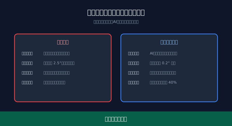
Measured data from a large steel structure plant by Kelude Heavy Industry shows: Under a 50t full load condition, without the anti-sway system, the post-braking sway angle reached 3.5° with a stabilization time of 18s. With the AI anti-sway system active, the angle dropped to 0.2°, and stabilization time shortened to 3.5s, significantly boosting positioning efficiency.
Performance evaluation assesses not just anti-sway efficacy but also its impact on overall cycle time. Data indicates that although input shaping adds approximately 1.5s to each acceleration/deceleration phase, the elimination of waiting time for stabilization reduces the total single-lift cycle time by 40%.
⚠️ Note
Once operational, a scheduled maintenance plan is mandatory. We recommend cleaning the lenses of the Laser Rangefinder and vision camera every 3 months and recalibrating sensor zeros to prevent measurement drift caused by dust accumulation or mechanical loosening.
FAQ
Q: Does the anti-sway system have specific requirements for wire rope length?
A: Yes. The anti-sway algorithm relies on accurate rope length data to calculate the sway period. Typically, the wire rope length should be over 5 meters, with variations not exceeding 20% of the set value. If the rope is too short or varies frequently, a Laser Distance Sensor is required for real-time dynamic compensation; otherwise, anti-sway effectiveness will be compromised.
Q: After retrofitting an AI anti-sway system, is it necessary to upgrade the Frequency Inverter power?
A: Generally, no additional power capacity is required. The anti-sway algorithm primarily suppresses load swing by optimizing the acceleration and deceleration curves of the Variable Frequency Drive (VFD), without increasing the motor's peak load. As long as the existing VFD capacity meets the requirements for Rated Lifting Capacity and Travel Speed, it can directly accept anti-sway control commands without needing extra power upgrades.
Q: What is the estimated budget for a complete AI anti-sway system retrofit?
A: The budget depends on the crane’s lifting capacity and sensor configuration. For a 10-ton overhead crane, the hardware cost for adding high-precision Encoders and vision modules is approximately $4,500–$7,500. Including software commissioning fees, the total investment is subject to the actual contract. Typically, the ROI is achieved within 1 to 2 years through reduced material loss and improved operational efficiency.
Q: Can the anti-sway system operate normally in high-temperature or dusty environments?
A: Yes, provided that sensors with appropriate Protection Ratings (IP) are selected. In workshops where temperatures exceed 50°C (122°F) or dust concentration is high, we recommend using Laser Rangefinders and industrial-grade AI vision cameras with an IP65 rating or higher. Additionally, heat dissipation or air-purging devices should be installed to ensure the stability of data acquisition.
The transition from basic mechanical formulas to AI control parameters represents not only an algorithmic victory but also the deep integration of machinery manufacturing and information technology. Kelude Heavy Industry has accumulated extensive practical experience in heavy-load customization, providing clients with one-stop anti-sway solutions ranging from mechanical modeling and hardware selection to on-site commissioning, helping enterprises achieve dual improvements in safety and efficiency.
