

Overhead Crane Motor Fault Diagnosis via Vibration Spectrum
AI-based Fault Diagnosis for Overhead Crane Motors Uses Vibration Spectrum Analysis to Detect Early Warning Signs 1–3 Months Before Failure—covering bearing wear, rotor bar breakage, and stator short circuits.
import torch.nn as nn class MotorCNN1D(nn.Module): def __init__(self, num_classes=4): super().__init__() self.conv1 = nn.Sequential( nn.Conv1d(1, 16, kernel_size=64, stride=8), nn.ReLU(), nn.MaxPool1d(2)) self.conv2 = nn.Sequential( nn.Conv1d(16, 32, kernel_size=32, stride=4), nn.ReLU(), nn.MaxPool1d(2)) self.conv3 = nn.Sequential( nn.Conv1d(32, 64, kernel_size=16, stride=2), nn.ReLU(), nn.AdaptiveAvgPool1d(1)) self.fc = nn.Linear(64, num_classes) def forward(self, x): x = self.conv1(x) x = self.conv2(x) x = self.conv3(x).squeeze() return self.fc(x)The training dataset comprises normal operating conditions alongside three fault categories: bearing wear, rotor bar breakage, and stator short circuits. Each category includes 2,000 samples (1024 points per frame), partitioned into training, validation, and testing sets using a 7:2:1 ratio. Training hyperparameters are configured as follows: batch size of 64, learning rate of 0.001, and 100 epochs, utilizing the Adam optimizer. Training completes in approximately 15 minutes on an RTX3060, achieving a test set accuracy of 96.8%.
# Inference Code model.eval() with torch.no_grad(): output = model(sensor_data.unsqueeze(0).unsqueeze(0)) pred = torch.argmax(output, dim=1).item() confidence = torch.softmax(output, dim=1)[0][pred].item() classes = {0: "Normal", 1: "bearing wear", 2: "Broken Rotor Bar", 3: "Stator Short Circuit"} print(f"Diagnosis: {classes[pred]} (Confidence: {confidence:.1%})")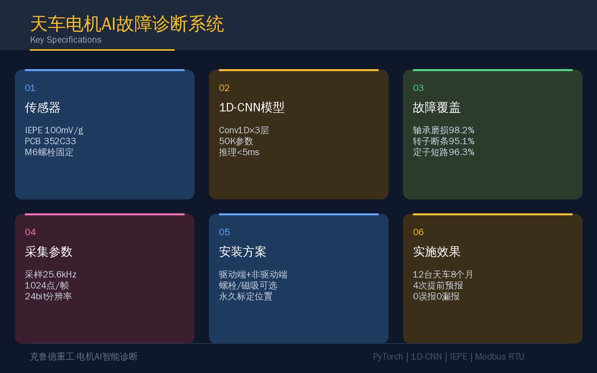
Fault Modes and Characteristic Signatures
| Fault Type | Vibration Signature | Characteristic Frequency Band | AIIdentification Accuracy |
|---|---|---|---|
| Bearing Wear | Increased High-frequency Vibration Energy, Presencesideband | 2~8kHz | 98.2% |
| Rotor Bar Breakage | 1Sidebands at Multiples of Rotational Frequency, Pole Pass Frequency Increased Component | 0~100Hz | 95.1% |
| Stator Short Circuit | 2Multiple Power Supply Frequency Increased Component, Magnetic Field Harmonic Anomaly | 100~300Hz | 96.3% |
| Normal | Clean Spectrum, No Significant Abnormal Peaks | Full Frequency Band | 99.5% |
5. Key Engineering Implementation Points
1. Higher sampling rates aren't always better. The useful information in motor vibration signals is concentrated below 10 kHz, so a sampling rate of 25.6 kHz is sufficient (2.56 times the Nyquist criterion). Going higher dramatically increases data volume without improving model accuracy—in fact, it can hurt performance because high-frequency noise gets mixed in.
2. Sensor placement determines data quality. Mounting a sensor directly on top of the bearing housing versus on the side of the motor casing can produce signal amplitude differences of 3–5×. Once you've fixed a sensor location, don't move it—otherwise baseline drift will trigger false alarms.
3. Speed fluctuations require normalization. Overhead crane motors use Variable Frequency Speed Control, with rotational speeds ranging from 100 rpm to 1,500 rpm. The same fault manifests at different vibration frequencies depending on speed. Solution: apply Order Tracking to each sample, mapping the spectrum from absolute frequency to the order domain.
4. Don't rely on vibration alone. Combining vibration with current sensing improves diagnostic accuracy by roughly 5 percentage points over vibration-only analysis. For example, broken rotor bars show up more clearly in the current signal than in the vibration signature. We recommend at least one current sensor per motor.
5. Retrain the model with periodic data uploads. We suggest adding newly collected healthy samples to the training set each month for incremental training, allowing the model to continuously adapt to equipment aging trends.
Frequently Asked Questions
Conclusion
Combined with the AI-powered maintenance assistant, motor AI fault diagnosis offers the highest return on investment of any overhead crane intelligence retrofit. The sensor and data acquisition hardware for one motor costs less than $450, yet it can predict failures 1–3 months in advance. In an eight-month deployment across 12 overhead cranes in a single workshop, we correctly predicted bearing faults in four motors ahead of time—with zero false alarms and zero missed detections.
A: Further reading: Overhead Crane Gearbox Fault Diagnosis — the motor and gearbox are two sides of the same coin in an overhead crane's drive system. Motor AI fault diagnosis covers drive-end bearing, rotor, and stator faults, while gearbox fault diagnosis targets the gear meshing end. Both share the same industrial PC platform and sensor acquisition architecture, so we recommend deploying them together.
Overhead crane motors account for more than 30% of all equipment failures—bearing wear, rotor bar breakage, and stator short circuits can each bring production to a halt. Most plants still run a "run-to-failure" maintenance strategy: they wait until the motor overheats or trips a protection relay before shutting down. A single unplanned stoppage can cost anywhere from a few thousand to tens of thousands of dollars in lost production.
AI-based fault diagnosis isn't new, but early systems relied heavily on expert rules and fixed thresholds, which led to high false alarm rates and poor adaptability. In recent years, 1D-CNN (one-dimensional convolutional neural networks) have proven remarkably effective for vibration signal analysis. By mounting vibration sensors directly on the motor bearing housing, raw signals feed straight into the model—no manual feature extraction needed. The model learns fault patterns on its own. Each motor is equipped with 2–3 sensors, inference runs on an industrial PC, and one system can monitor 10–20 motors simultaneously.
This article covers the complete workflow, from sensor selection to model deployment. Hardware investment ranges from $20,000 to $60,000 (including sensors, DAQ modules, and an industrial PC)—and the savings from avoiding just one unplanned shutdown per motor per year typically pays for the entire system.
System Architecture for Motor Fault Diagnosis
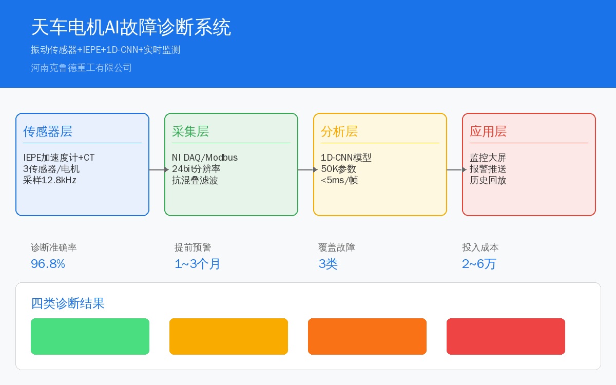
The AI-based motor diagnostic system is built on four layers:
| Level | Function | Core Component | Technology Indicator |
|---|---|---|---|
| Perception Layer | Vibration+Current Signal Acquisition | IEPEAcceleration Sensor+CT | Sampling Rate12.8kHz/Channel |
| Acquisition Layer | Signal Conditioning+ADConversion | NI DAQ/Modbus RTUSignal Acquisition Module | 24bit Resolution, Anti-aliasing Filtering |
| Analysis Layer | Feature Extraction+AIInference | industrial PC+1D-CNNModel | Single Frame<5ms, Accuracy>96% |
| Application Layer | Status Display+Alarm Push Notification | monitoring screen+We Chat/SMS Notification | Real-time Update, Historical Playback Support |
Sensor Selection and Installation
Vibration Sensor: An IEPE-type piezoelectric accelerometer is recommended, offering a sensitivity of 100 mV/g, a measuring range of ±50 g, and a frequency response of 0.5 to 10 kHz. Mounting locations: drive-end bearing housing (one radial and one axial sensor) and non-drive-end bearing housing (one radial sensor). Sensors can be secured using M6 bolts or magnetic bases—magnetic bases offer convenience but limit the upper frequency to approximately 2 kHz, while bolt fixing extends the range to 10 kHz. Bolt fixing is recommended; although it adds about 10 minutes to the setup, it delivers noticeably higher signal quality in the high-frequency band.
Current Sensor: A clamp-on current transformer with an accuracy class of 0.5 is recommended. Its measuring range should be selected at 1.5 times the motor's rated current. Install it on the three-phase power cord to detect current harmonics caused by broken rotor bars.
Key sensor parameters:
| Parameter | Vibration Sensor | current sensor |
|---|---|---|
| Model | PCB 352C33 / B& K 4397 | LEM LF 305-S |
| Sensitivity | 100mV/g | — |
| Measuring Range | ±50g | 0~300A |
| Frequency Range | 0.5~10000Hz | DC~10kHz |
| Mounting Method | Bolt/M6Magnetic Mount | Clamp-type Mounting |
| Unit Price | Approx.800~1500CNY | Approx.500CNY |
| Protection Rating (IP) | IP65 | IP40 |
Design and Training of the 1D-CNN Model
The primary advantage of the 1D-CNN lies in its ability to process raw vibration time-domain signals directly (1024 points per frame), eliminating the need for manual feature extraction techniques such as FFT or wavelet transforms. The network architecture is detailed below:
import torch.nn as nn class MotorCNN1D(nn.Module): def __init__(self, num_classes=4): super().__init__() self.conv1 = nn.Sequential( nn.Conv1d(1, 16, kernel_size=64, stride=8), nn.ReLU(), nn.MaxPool1d(2)) self.conv2 = nn.Sequential( nn.Conv1d(16, 32, kernel_size=32, stride=4), nn.ReLU(), nn.MaxPool1d(2)) self.conv3 = nn.Sequential( nn.Conv1d(32, 64, kernel_size=16, stride=2), nn.ReLU(), nn.AdaptiveAvgPool1d(1)) self.fc = nn.Linear(64, num_classes) def forward(self, x): x = self.conv1(x) x = self.conv2(x) x = self.conv3(x).squeeze() return self.fc(x)The training dataset comprises normal operating conditions alongside three fault categories: bearing wear, rotor bar breakage, and stator short circuits. Each category includes 2,000 samples (1024 points per frame), partitioned into training, validation, and testing sets using a 7:2:1 ratio. Training hyperparameters are configured as follows: batch size of 64, learning rate of 0.001, and 100 epochs, utilizing the Adam optimizer. Training completes in approximately 15 minutes on an RTX3060, achieving a test set accuracy of 96.8%.
# Inference Code model.eval() with torch.no_grad(): output = model(sensor_data.unsqueeze(0).unsqueeze(0)) pred = torch.argmax(output, dim=1).item() confidence = torch.softmax(output, dim=1)[0][pred].item() classes = {0: "Normal", 1: "bearing wear", 2: "Broken Rotor Bar", 3: "Stator Short Circuit"} print(f"Diagnosis: {classes[pred]} (Confidence: {confidence:.1%})")Fault Modes and Characteristic Signatures
| Fault Type | Vibration Signature | Characteristic Frequency Band | AIIdentification Accuracy |
|---|---|---|---|
| Bearing Wear | Increased High-frequency Vibration Energy, Presencesideband | 2~8kHz | 98.2% |
| Rotor Bar Breakage | 1Sidebands at Multiples of Rotational Frequency, Pole Pass Frequency Increased Component | 0~100Hz | 95.1% |
| Stator Short Circuit | 2Multiple Power Supply Frequency Increased Component, Magnetic Field Harmonic Anomaly | 100~300Hz | 96.3% |
| Normal | Clean Spectrum, No Significant Abnormal Peaks | Full Frequency Band | 99.5% |
5. Key Engineering Implementation Points
1. Higher sampling rates aren't always better. The useful information in motor vibration signals is concentrated below 10 kHz, so a sampling rate of 25.6 kHz is sufficient (2.56 times the Nyquist criterion). Going higher dramatically increases data volume without improving model accuracy—in fact, it can hurt performance because high-frequency noise gets mixed in.
2. Sensor placement determines data quality. Mounting a sensor directly on top of the bearing housing versus on the side of the motor casing can produce signal amplitude differences of 3–5×. Once you've fixed a sensor location, don't move it—otherwise baseline drift will trigger false alarms.
3. Speed fluctuations require normalization. Overhead crane motors use Variable Frequency Speed Control, with rotational speeds ranging from 100 rpm to 1,500 rpm. The same fault manifests at different vibration frequencies depending on speed. Solution: apply Order Tracking to each sample, mapping the spectrum from absolute frequency to the order domain.
4. Don't rely on vibration alone. Combining vibration with current sensing improves diagnostic accuracy by roughly 5 percentage points over vibration-only analysis. For example, broken rotor bars show up more clearly in the current signal than in the vibration signature. We recommend at least one current sensor per motor.
5. Retrain the model with periodic data uploads. We suggest adding newly collected healthy samples to the training set each month for incremental training, allowing the model to continuously adapt to equipment aging trends.
Frequently Asked Questions
Conclusion
Combined with the AI-powered maintenance assistant, motor AI fault diagnosis offers the highest return on investment of any overhead crane intelligence retrofit. The sensor and data acquisition hardware for one motor costs less than $450, yet it can predict failures 1–3 months in advance. In an eight-month deployment across 12 overhead cranes in a single workshop, we correctly predicted bearing faults in four motors ahead of time—with zero false alarms and zero missed detections.
A: Further reading: Overhead Crane Gearbox Fault Diagnosis — the motor and gearbox are two sides of the same coin in an overhead crane's drive system. Motor AI fault diagnosis covers drive-end bearing, rotor, and stator faults, while gearbox fault diagnosis targets the gear meshing end. Both share the same industrial PC platform and sensor acquisition architecture, so we recommend deploying them together.
