

Crane Travel Mechanism Installation & Commissioning Guide
📋 Key Takeaways
The installation and commissioning of the crane travel mechanism (bridge travel and trolley travel) is a critical step in final machine delivery. This article covers six tolerance standards for rail installation, four precision acceptance criteria for wheel blocks, a three-step drive shaft alignment inspection method, and seven acceptance indicators for commissioning — all in line with the ISO 4301 design standard and the FEM 1.001 test procedure requirements. Installation quality directly affects flange rubbing, running stability, and mechanism service life: a span deviation of just 1 mm beyond tolerance can triple the wear rate of wheel flanges, while a coupling coaxiality deviation exceeding 0.1 mm can increase reducer vibration levels by over 40%. We recommend documenting each acceptance step with photos and completing the three-stage test sequence (no-load, static load, and dynamic load) before putting the crane into service.
What Preparations Are Required Before Installing a Crane Travel Mechanism?
Four essential preparation steps must be completed before installation begins — none can be skipped:
1. Steel Structure Foundation Inspection: Verify that the top elevation deviation of the runway beam in the factory building does not exceed ±5 mm, the runway beam centerline offset from the positioning axis is ≤3 mm, and the position deviation of anchor bolts or reserved holes is ≤2 mm. Installation may only proceed after the concrete has reached 100% of its design strength.
2. Equipment Unpacking and Inspection: Check the model numbers and quantities of the drive motor, reducer, brake, coupling, and wheel blocks against the packing list. Inspect castings for cracks and sand holes, and machined surfaces for corrosion or damage. Motor insulation resistance must be ≥0.5 MΩ (measured with a 500 V megohmmeter), and the reducer's factory run-in test report should be reviewed.
3. Tooling and Instrument Preparation: Level instrument (accuracy ±0.5 mm/30 m), theodolite, dial indicator (0.01 mm resolution), feeler gauge (0.02–1 mm), torque wrench (within calibration validity), and laser shaft alignment tool (or dial micrometer alignment bracket). The rated capacity of the lifting equipment must be at least 1.25 times the weight of the heaviest single component.
4. Construction Plan Briefing: Define the installation sequence (rails first, then crane bridge, then trolley), prepare the welding procedure qualification record (WPQR), designate hoisting safety zones, and implement fall protection measures for work at height. A dedicated installation plan must be prepared in accordance with Chapter 9 of the ISO 4301 Crane Design Standard.
Bridge cranes delivered by Kelude are pre-assembled and run-in tested at the factory, so on-site installation only requires shaft alignment and bolt tightening — reducing on-site commissioning work by 80%.
What Are the 6 Critical Rail Installation Tolerances for Bridge Travel?
Rail installation is the foundation of the entire travel mechanism. The following six parameters must be checked and accepted one by one:
1. Rail Span Deviation: ≤±5 mm (≤±3 mm when span S ≤ 19.5 m). Measure with a steel tape and spring scale (tension 150 N), recording the deviation direction at every 6 m interval.
2. Rail Top Elevation Difference: The elevation difference between the two rail tops at the same cross-section must be ≤10 mm (measured at every 2 m along the rail length). When S ≤ 19.5 m, the limit is ≤3 mm. Exceeding this tolerance causes uneven wheel load distribution and accelerates single-side flange wear.
3. Rail Joint Gap: 1–3 mm (for thermal expansion). The vertical step at the joint must be ≤1 mm, and the lateral offset ≤1 mm. Direct welding across rail joints is strictly prohibited — fishplates with bolted connections must be used.
4. Rail Straightness: Horizontal straightness ≤2 mm per 2 m over the full length; vertical straightness ≤2 mm per 2 m over the full length. Check with a theodolite or by stretching a 0.5 mm diameter piano wire under 150 N tension.
5. Rail Fixing Method: Clamp plate spacing ≤600 mm (≤500 mm for QU70 rails and above). Clamp plate bolt pre-tightening torque per design values (typically 200–250 N·m for M20 bolts). Welded clamp plates must undergo post-weld flaw detection.
6. Rail Grounding: Reliable grounding at both rail ends and at intermediate points (spacing ≤50 m), with grounding resistance ≤4 Ω. Rail joints must be bridged with bonding conductors (≥16 mm² copper braided strap) to ensure electrical continuity.
Per FEM 1.001 Crane Test Specification and Procedure, a no-load test run must be performed after rail installation, with rail deviations re-measured over the full travel range and documented in an acceptance report.
4 Wheel Block Installation Accuracy Standards for Crane Travel Mechanisms
Wheel block installation accuracy is the deciding factor in whether the travel mechanism suffers from wheel rail gnawing. In severe cases, flange wear can reach 5–8 times the normal rate, rendering both the wheel and the rail unusable. The four acceptance standards are as follows:
1. Wheel Horizontal Inclination: ≤L/1000 (where L is the measurement length across the wheel tread width). Excessive horizontal inclination causes the wheel to "track crooked," creating continuous friction between the flange and the rail side. Measure with a wire line and inside micrometer at four points (top, bottom, left, right) on the wheel end face.
2. Wheel Vertical Inclination: ≤1/400 (i.e., the lower edge of the wheel end face tilts inward by no more than 0.25%). A slight conical tread contact is acceptable, but outward tilting of the upper edge is strictly prohibited — it causes concentrated loading on the outer flange and creates a derailment risk. Measure with a frame spirit level on the wheel end face.
3. Wheel Alignment Difference: The alignment difference between wheels on the same end carriage must be ≤2 mm (bridge crane) or ≤3 mm (gantry crane). Exceeding this tolerance leaves some wheels partially unloaded or causes uneven wheel load distribution, resulting in running vibration and localized rail crushing.
4. Wheel Tread Elevation Difference: The tread elevation difference between two wheels on the same end carriage must be ≤0.5 mm. If out of tolerance, adjust by adding shims under the angle bearing housing. Shims must be stainless steel (to prevent corrosion and loosening), with a total thickness ≤5 mm and no more than 3 layers.
After installation, rotate the wheel blocks manually to verify smooth, free rotation without binding, and confirm axial play ≤0.5 mm. Kelude's standard angle bearing housing wheel blocks are matched and lapped at the factory, so on-site installation directly meets the above accuracy standards.
4 Crane Travel Drive Types Compared: Centralized, Separate, VFD, and Servo
The choice of drive configuration for a crane travel mechanism depends on span, lifting capacity, work duty, and budget. Below is a detailed comparison of the four mainstream drive types:
| Drive Mode | Synchronization Accuracy | Applicable to Span(m) |
|---|---|---|
| Centralized Drive(Single Motor+Drive Shaft) | Machinery Forced Synchronization, Both Sides Deviation≈0 | ≤19.5m(Drive Shaft Torsional Limitation) |
| Separate Drive(Dual Motor Independent) | Electrical synchronization, Deviation≤2% | 19.5~40m(General Solution) |
| Variable Frequency Speed Control Centralized Drive(VFD) | Closed-loop Vector Synchronization, Deviation≤0.5% | 10~60m(High Accuracy Application) |
| Servo Precision Drive(PLC+Encoder) | Full Closed-Loop Control, Deviation≤0.01% | Unlimited(nuclear power/Precision Assembly Applicable to) |
The drive selection decision chain starts with confirming the crane service rating (A1~A8), then selecting the drive configuration based on span. For light and medium duty classes A1~A4, either centralized drive or individual drive is sufficient; for A5 and above, variable-frequency drive (VFD) is recommended. For special applications such as nuclear power plants and precision assembly lines, servo drive is the preferred choice. Kelude Heavy Industry equips all bridge cranes rated A5 and above with individual drives featuring variable-frequency speed control as standard, delivering stepless speed control from 0 to 50 m/min with anti-sway control.
Crane Travel Mechanism Coupling Alignment: 3-Step Inspection Method
Coupling misalignment is the leading cause of high-speed shaft breakage in reducers and premature bearing failure. Statistics show that when coupling misalignment exceeds 0.1 mm, bearing service life drops to one-eighth of its normal value; at misalignment beyond 0.3 mm, seals fail within 100 operating hours. Perform the following 3-step inspection and correction procedure:
Step 1 — Rough Alignment (Visual + Straightedge Method): Hold a straightedge against the outer circumference of both coupling halves and visually check that the gap is uniform around the entire circumference. Loosen the motor base bolts and adjust the motor position until both shafts are roughly aligned. Permissible deviation at this stage: ≤0.5 mm.
Step 2 — Radial Deviation Check (Dial Indicator Method): Mount a magnetic-base dial indicator on the motor-side coupling half, with the indicator plunger perpendicular to the outer surface of the reducer-side coupling half. Rotate the motor shaft 360° and record readings at the top, bottom, left, and right positions. Radial deviation = (top − bottom)/2 or (left − right)/2. Acceptance criteria: ≤0.05 mm for gear couplings, or ≤0.03 mm for diaphragm couplings.
Step 3 — Angular Deviation Check (Gap Method): Using a feeler gauge, measure the gap between the coupling faces at four positions: 0°, 90°, 180°, and 270°. The maximum difference between gap readings is the angular deviation. Acceptance criteria: ≤0.1 mm per 100 mm diameter for gear couplings, or ≤0.05 mm per 100 mm diameter for flexible couplings.
Correction Procedure: For radial deviation, adjust the motor base shims to raise or lower the motor, and shift it laterally to correct horizontal position. For angular deviation, fine-tune the preload on the front/rear motor base bolts. After all adjustments are complete, tighten the base bolts diagonally (torque per specification) and re-check to confirm that bolt tightening has not introduced new deviation. Kelude Heavy Industry performs factory pre-alignment of the motor–reducer–brake assembly on all travel mechanisms before shipment; on-site, only a check for transport-induced shift is required.
7-Point Acceptance Standard for Crane Travel Mechanism Commissioning
After installation of the travel mechanism, perform commissioning and inspection against the following 7 items and document the results in an acceptance report:
| Inspection Project | Acceptance Criteria | Detection Method |
|---|---|---|
| Travel Speed Deviation | Measured Value/Design Value = 0.9~1.1 | Photoelectric Rotational speed Wheel Measurement Rotational speed, Conversion Line Start Button |
| Braking Droop | Operation Braking≤Rated Start Button/100(mm) | Emergency Stop after Full-speed Operation, Measure Coasting Distance |
| Operating Noise | ≤85dB(A)(Cabin / Operator Cab)≤90dB(A)(At Machine) | sound level meter AWeighted, Distance from Sound Source1mMeasurement at |
| Bearing Temperature Rise | ≤40K, Maximum≤75℃ | Continuous Operation with Infrared Thermometer30min Post-measurement |
| Wheel rail gnawing / flange rubbing Inspection | No Continuous Side Contact and Abnormal noise | Full-travel Observation Wheel flangeand Crane Rail Clearance |
| Limit switch | Post-trigger Coasting Distance≤150mm | Full-speed Impact against Limit, Measure Coasting Distance after Power-off |
Kelude Heavy Industry delivers travel mechanisms equipped as standard with laser distance measurement anti-collision systems and infrared thermal imaging online monitoring modules. Bearing temperature, vibration values, brake wear, and other data can be uploaded in real time to the GB/T 28264 Safety Monitoring and Management System platform, enabling preventive maintenance and fault prediction.
≤5mm
Span Deviation
Per GB/T 10183
≤0.05mm
Coupling Shaft Alignment
Radial Runout Tolerance
≥1.25×
Brake Safety Factor
Travel Mechanism Braking
L/1000
Wheel Horizontal Skew
Key Anti-Flange-Rubbing Indicator
≤90dB(A)
Noise Limit
A-Weighted at 1m from Unit
≤40K
Bearing Temperature Rise Limit
Max Temp ≤75°C
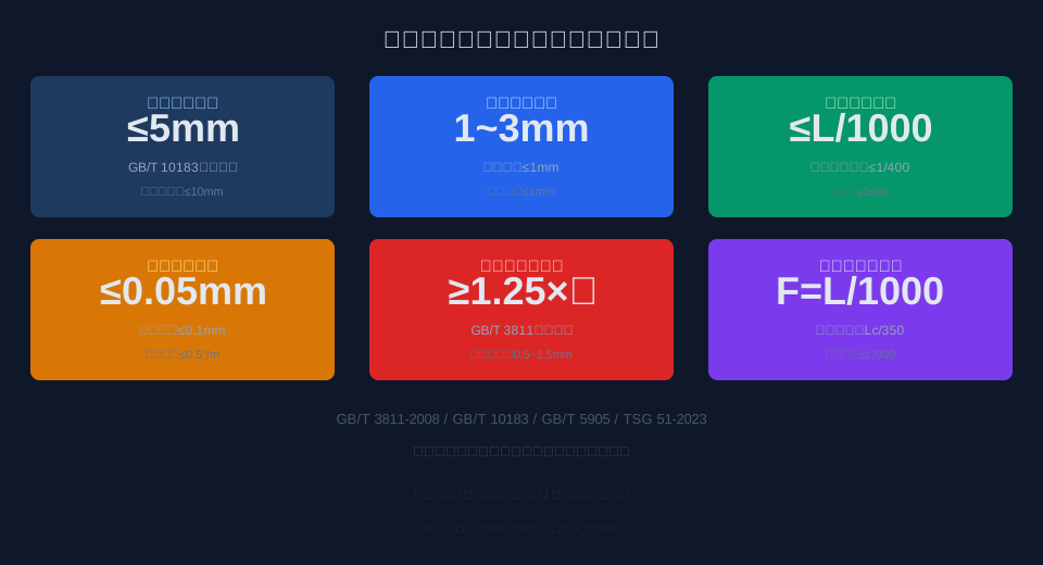
After installation and commissioning, the system enters the trial run phase. The no-load test run lasts at least 30 minutes, checking for abnormal noise, sticking, or excessive temperature rise. The static load test is performed at 1.25 times rated load, verifying main girder deflection does not exceed L/800. The dynamic load test runs repeatedly at 1.1 times rated load to confirm proper operation of brakes, limit switches, and electrical protection. Only after all tests pass is the delivery acceptance report issued.
📖 Related Reading
Explore these technical articles covering crane design, selection, installation, and commissioning:
ISO 4301 Crane Design Standard: 9 Load Combinations and Work Duty Selection from M6 to M7
FEM 1.001 Crane Test Specification: 3 Load Test Procedures and 6 Acceptance Criteria
GB/T 28264 Safety Monitoring and Management System for Lifting Appliances — Standard Overview
Common Questions on Crane Travel Mechanism Installation & Commissioning
Q: What is the difference between individually driven and centrally driven crane travel mechanisms?
A: In a centrally driven system, a single electric motor drives both wheels through a long drive shaft, offering high mechanical synchronization accuracy (near-zero deviation between sides). However, torsional stiffness limits this design to spans of 19.5m or less. Individually driven systems use a separate motor for each side, with electrical control ensuring synchronization (deviation ≤2%), suitable for spans from 19.5m to 40m and easier to install and maintain. Currently, over 80% of newly installed overhead cranes use individual drives, and it is recommended to equip units rated M8 and above with VFDs for soft start and stop.
Q: What specific requirements does ISO 4301 impose on travel mechanism brakes?
A: Clause 5.8 of ISO 4301 requires a brake safety factor of at least 1.25 (braking torque divided by rated travel resistance torque), and brakes must be fail-safe (spring-applied, power-off braking). Outdoor cranes must be fitted with wind protection devices (rail clamps or anchor devices), with an anti-skid safety factor of at least 1.1. Brake friction linings must be replaced when wear reaches 50% of original thickness, and brake clearance should be maintained between 0.5mm and 1.5mm. TSG 51-2023 further mandates functional testing of travel mechanism brakes at least once per quarter, with results documented.
Q: How can wheel flange rubbing (skewing) be permanently corrected?
A: Diagnosing wheel rail gnawing requires a systematic approach: check the rail first, then the wheels, and finally the structural frame. Step 1: Measure crane rail span deviation (≤±5mm) and straightness (≤2mm/2m) to rule out rail issues. Step 2: Check wheel horizontal skew (≤L/1000) using a dial indicator or laser alignment tool to measure four-point deviation on the wheel end face. Step 3: Measure wheel position offset (≤2mm) and tread surface height difference (≤0.5mm). Step 4: Check bridge diagonal deviation (≤5mm) — structural deformation causing flange rubbing requires steel structure correction. In practice, 70% of wheel rail gnawing cases stem from rail installation tolerance issues, 20% from wheel skew, and 10% from structural deformation.
Q: How much does installation & commissioning of a crane travel mechanism typically cost?
A: The cost of travel mechanism installation & commissioning consists of three components: labor (2–4 technicians × 3–7 days, approximately 8,000–20,000 CNY / $1,200–$3,000, depending on lifting capacity and span), instrument rental (level instrument + theodolite + laser alignment tool, approximately 2,000–5,000 CNY / $300–$740), and auxiliary materials (shims, bolts, grease, etc., approximately 1,000–3,000 CNY / $150–$440). For a general purpose bridge crane with lifting capacity ≤20t and span ≤22.5m, the full installation & commissioning package typically ranges from 15,000–30,000 CNY / $2,200–$4,400. Kelude Heavy Industry offers factory pre-commissioning services (including shaft alignment, electrical testing, and a 48-hour run-in test), so on-site work is limited to final acceptance testing and adjustments.
