

Millimeter-Level Crane Positioning via Machine Vision
📋 Key Summary
By integrating industrial-grade binocular cameras with deep learning algorithms, machine vision empowers European Standard Double-Girder Cranes (50t–300t) with autonomous object recognition and millimeter-level positioning capabilities. The system captures real-time cargo profiles and calculates 3D spatial coordinates to strictly control the lifting spreader alignment error within ±2mm. In challenging environments characterized by complex lighting and workshop dust, the vision-guided positioning system achieves a response time of under 80ms, significantly boosting operational efficiency in heavy manufacturing and automated warehousing.
This article provides an in-depth analysis of the core algorithmic logic behind machine vision for crane auto-search and millimeter-level positioning. It explores binocular vision calculation methods and leverages practical engineering case studies and performance comparisons from Kelude Heavy Industry to comprehensively explain the technical details of AI-enabled high-end lifting equipment.
Core Algorithm Logic for Vision-Guided Auto-Search and Millimeter-Level Positioning
In traditional crane operations, operators rely on visual inspection and manual control to align the lifting spreader. This not only limits efficiency but also induces visual fatigue, particularly in large workshops or during night shifts. With the introduction of machine vision technology, cranes are equipped with "eyes" and a "brain." Industrial-grade cameras installed beneath the main girder or above the lifting spreader capture real-time image data of the working area. When developing 50t–300t European Standard Double-Girder Cranes, Kelude's technical team deeply integrated vision algorithms into the PLC Control hub, achieving fully automatic closed-loop control from target identification to Path Planning.
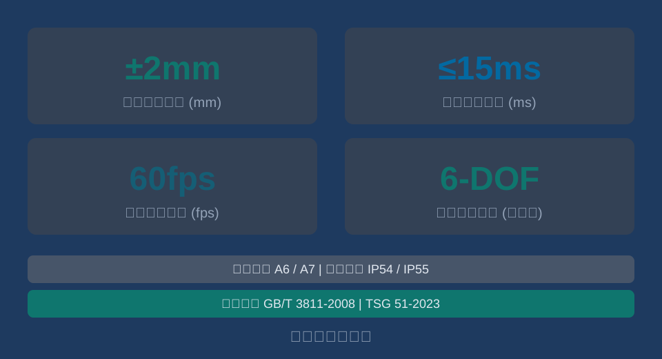
The core of modern vision positioning systems lies in the real-time performance of image processing algorithms. Taking Kelude's standard vision module as an example, it utilizes 4K Resolution industrial cameras with a stable image acquisition frame rate of 60fps. This enables the system to process 60 HD frames per second, keeping single-frame image processing and feature extraction latency under 15ms. Through edge computing nodes, the system rapidly filters background noise to precisely extract cargo edge profiles and feature points.
"According to statistics from the China National Heavy Machinery Industry Association, in automated warehousing projects utilizing vision guidance, the average cycle time for single lifting and transport operations has been reduced by 22%, while the rate of manual intervention has dropped by over 85%."
⚠️ Note
The accuracy of vision algorithms heavily depends on image quality. In workshop environments with high dust concentration or strong backlighting, it is recommended to install polarizing filters on camera lenses and equip auxiliary LED ring lights to ensure the stability of feature extraction.
The algorithmic logic primarily consists of two stages: object detection and pose estimation. During object detection, a deep learning model based on convolutional neural networks is used to generate bounding boxes for the cargo. In the pose estimation stage, the PnP algorithm, combined with the camera's intrinsic parameter matrix, calculates the precise 3D coordinates of the cargo. This logic applies not only to regular-shaped steel coils and Steel Plates but, through specific model training, can also effectively identify irregular castings. Kelude's technical team completes model training and Parameter optimization in the laboratory prior to deployment, ensuring millimeter-level recognition accuracy upon site installation.
Real-Time Calculation of Lifting Spreader Spatial Attitude Based on Deep Learning and Binocular Vision
Achieving millimeter-level precision requires more than just 2D images from monocular cameras; depth information is essential. Binocular vision technology, which mimics human binocular disparity, is key to solving this. In the Hoisting mechanism and Trolley Travel Mechanism of European Standard Double-Girder Cranes, the binocular vision system calculates the relative spatial attitude between the lifting spreader and the target cargo in real time.
Kelude's binocular vision system sets the baseline distance between left and right cameras at 200mm, covering a depth measurement range of 0.5m to 15m. Within a 5m working distance, the system's depth measurement error is controlled within ±2mm. This high-precision spatial calculation relies on deep learning algorithms for real-time correction of image distortion. The built-in FPGA hardware acceleration module completes stereo matching and disparity map generation for left and right images within 8ms.
After obtaining precise 3D coordinates, the system compensates for attitude using the crane's kinematic model. When the lifting spreader sways during high-speed operation, the vision system measures the absolute coordinate of the cargo, whereas the control system requires coordinates relative to the spreader. At this point, the system invokes the real-time state observer from the AI anti-sway algorithm, integrating sway angle and displacement data into the vision calculation model to output precise Closed-Loop Control commands.
"In the field of heavy equipment manufacturing, the assembly and alignment of large forgings impose strict requirements on spatial attitude. Field tests show that a fused calculation solution combining binocular vision with an inertial measurement unit can improve the pitch and yaw angle control accuracy of the lifting spreader to within 0.1°."
Another challenge in spatial attitude calculation is feature loss in dynamic environments. When cargo is partially occluded or reflective, binocular matching may yield errors. To address this, Kelude introduces multi-object tracking mechanisms and Kalman filter prediction into its algorithms. When visual features are temporarily lost, the system predicts the next frame's cargo position based on previous motion trajectories, ensuring continuity of control commands. This fusion strategy of vision and prediction greatly enhances the robustness of the system under complex operating conditions.
Engineering Case Study: Vision Positioning Systems in Complex Operating Conditions
The superiority of theoretical algorithms must ultimately be validated through engineering practice. In crane automation retrofit projects, vision positioning systems must perfectly match the mechanical braking and electrical drive systems of the crane. The following engineering case study details the collaborative control of vision positioning and mechanical braking, using the Crane Travel Mechanism of a 100t European Standard Double-Girder Crane as an example.
Assume the Long Travel Speed of this crane is 60m/min, equivalent to 1m/s in international units. When the vision system detects that the lifting spreader is 5m away from the target alignment point, it triggers a deceleration command; when the distance reduces to 1.5m, it triggers a stop command. At this moment, the bridge drive motor begins braking. Given that the comprehensive deceleration of the crane travel mechanism is set to 0.5m/s², the braking distance $s$ is calculated using the kinematic formula $s = v^2 / (2a)$. Substituting the values: $s = 1^2 / (2 \times 0.5) = 1m$.
This means that from the moment the stop command is triggered until the motor brakes completely, the crane bridge will coast forward by approximately 1 meter (3.28 feet). Therefore, to ensure the lifting spreader stops precisely at the target point, the vision system must issue the stop signal when it is 2.5 meters (8.2 feet) away—calculated as the sum of the anti-collision safety distance (1.5m) and the braking distance (1m). Additionally, considering the mechanical error in encoder feedback is typically ±5mm, the dynamic compensation capacity for the vision system should be set to 2mm.
When calculating the braking distance, a safety margin must also be factored in. According to specifications regarding anti-collision safety distance for cranes, under automated operation modes, the physical distance between the crane bridge and the rail end stop must not be less than 2 meters (6.56 feet). In the engineering case study above, if the target point is near the rail end, the vision system must perform real-time monitoring of the end-stop distance to ensure that the braking process does not result in an over-travel collision.
💡 Tip
In practical engineering applications, wheel slippage or uneven crane rails can cause actual deceleration to deviate from theoretical values. It is recommended to conduct at least 20 no-load and full-load braking tests during the commissioning stage to collect real-world deceleration data and dynamically adjust the braking distance compensation parameters in the PLC.
Beyond long travel, positioning accuracy of the hoisting mechanism is equally critical. For a 100-ton crane, the lifting speed is typically 5 m/min (approximately 0.083 m/s). Due to the heavy load and resulting inertia, the calculation of the hoisting braking distance must account for the elasticity of the wire rope. Kelude Heavy Industry incorporates the elastic elongation of the steel wire under full load (typically 0.5 mm/m) into the Z-axis compensation model for visual positioning in its engineering case studies, ensuring that vertical positioning accuracy also achieves millimeter-level precision.
Performance Comparison: Visual Positioning vs. Laser Distance Measurement in High-End Customization
In the field of crane automation positioning, laser distance sensors were once the mainstream solution. However, as high-end customization scenarios demand higher precision and flexibility, machine vision systems have gradually demonstrated irreplaceable advantages. To help clients better understand the technical differences between these two approaches, we provide a detailed performance comparison across multiple dimensions.
Traditional laser distance sensors calculate distance by emitting a laser beam and receiving the reflected light, with single-point measurement accuracy typically around ±5mm. In contrast, machine vision systems capture global images using area-scan cameras and extract multi-point features through algorithms, achieving a comprehensive positioning accuracy of up to ±2mm. Furthermore, while laser ranging only provides single coordinates in one or three dimensions and cannot identify cargo shape or attitude, vision systems simultaneously output the X, Y, and Z coordinates along with pitch, yaw, and roll angles.
To intuitively demonstrate the technical differences between these two positioning solutions, we have conducted a detailed comparison based on core dimensions such as accuracy, functionality, and environmental adaptability.
📊 Performance Comparison: Machine Vision Positioning System vs. Traditional Laser Ranging System
| Comparison Parameter | machine visionpositioning system | ConventionalLaser Distance MeasurementSystem |
|---|---|---|
| ComprehensivePositioning Accuracy | ±2mm | ±5mm |
| PoseIdentificationCapability | Support 6 DOF Calculation | Single-point Coordinate Support Only |
| Resistant toambient light interference | Strong(With Filtering and Algorithms) | Weak(Susceptible to Strong Light Interference) |
| Simultaneous Multi-targetIdentification | Support(All Targets in Frame) | Not Supported(Requires Addition ofSensor) |
The table below details the hardware configuration and implementation timeline differences for cranes with varying capacities equipped with a visual positioning system.
📊 Comparison of Hardware Configuration and Implementation Timeline for Crane Visual Positioning Systems by Capacity
| cranecapacity | cameraconfiguration solution | edge computing node | On-site Implementation Cycle |
|---|---|---|---|
| 50t European Standard Double-Girder | Monocular 4K + Assisted Binocular | Singlenode ARM Architecture | 5-7 Working Days |
| 100t European Standard Double-Girder | Global Binocular 4K + Depthcamera | Dualnode x86 Architecture | 7-10 Working Days |
| 200t~300t Custom | Multi-camera Array + LiDARFusion | industrial PCCluster + GPU Acceleration | 15-20 Working Days |
In high-end customization scenarios, such as nuclear power construction or aerospace component hoisting, equipment reliability requirements are exceptionally stringent. The vision system not only performs positioning but also conducts real-time monitoring of structural health conditions, including weld crack detection on the main girder. Through image comparison and analysis, it provides early warning for potential safety hazards. The visual positioning solution provided by Kelude Heavy Industry is not merely an upgrade to automation control but a critical component of full life cycle management. For specific projects, hardware configuration and renovation cost depend on site survey results and customization needs, subject to the actual contract.
FAQ
The following Q&A is based on Kelude Heavy Industry's practical delivery experience in European Standard Double-Girder crane retrofit projects, aiming to address common concerns regarding selection and application.
Q: What are the specific lighting conditions requirements for the machine vision positioning system in workshops?
A: The system features a wide dynamic range, capable of adapting to lighting variations from 50Lux to 50000Lux. However, in extreme environments with strong flickering light or local high reflection, it is recommended to retrofit polarizing filters or auxiliary uniform light sources to ensure the stability of image feature extraction.
Q: What are the Resolution and frame rate parameters of the visual positioning system cameras?
A: Kelude Heavy Industry's standard solution employs industrial camera with 4K Resolution, maintaining a stable frame rate of 60fps. For scenarios requiring extremely high dynamic response, optional 8K resolution, 120fps high-speed camera modules are available, with single-frame processing latency below 10ms.
Q: What is the approximate retrofit cost for adding a visual positioning system to a 50t crane?
A: Retrofit cost is influenced by the number of cameras, computing node configuration, and on-site construction difficulty. Typically, the basic visual renovation cost for a 50t European Standard Double-Girder Crane ranges from approximately $7,400 to $74,000. Specific Quotation requires integration with Site Survey results, subject to the actual contract.
Q: How does the vision system interact with the crane's anti-sway control system via data exchange?
A: The vision system transmits the Lifting spreader's real-time 3D coordinates and attitude angles to the PLC via Profinet or EtherCAT industrial Ethernet at a 10ms cycle. The PLC combines this with the anti-sway algorithm to dynamically adjust the Frequency Inverter output frequency, achieving closed-loop anti-sway control.
In summary, machine vision technology provides a high-precision perception foundation for crane automation, fundamentally transforming traditional operations that relied on manual experience. Kelude Heavy Industry is committed to the deep integration of cutting-edge AI algorithms with European Standard high-end manufacturing, providing customers with safe, efficient, and intelligent Material Handling solutions to facilitate the digital transformation and industrial upgrading of modern industrial logistics.
