

How AI Anti-Sway Algorithms Work in Intelligent Overhead Cranes
📋 Key Summary
Load sway is the root cause of slow positioning and unsafe operation in intelligent overhead cranes. This article breaks down the underlying logic of electronic anti-sway: trolley acceleration and deceleration generate inertial sway, rope length determines the sway period, and the anti-sway control algorithm essentially suppresses that sway at either the command level or the feedback level. It compares four mainstream approaches — input shaping, PID closed-loop, Fuzzy Logic Control, and model predictive control — in terms of residual sway angle, Positioning Accuracy, and sway settling time, and provides a decision path for selection based on capacity and positioning accuracy. Key conclusion: true anti-sway control relies on real-time computation by the control algorithm, not on simply slowing down; choose the right algorithm, and the crane gets more stable the longer it runs.
Many intelligent overhead cranes advertise "anti-sway" that isn't really anti-sway at all — the label says electronic anti-sway, but the actual effect is just slower acceleration and deceleration. The load stops swinging, but the price is a longer positioning cycle and a wrecked takt time. True electronic anti-sway relies on the control algorithm computing and canceling the sway state in real time — speed stays where it should be, and the sway angle still gets suppressed.
That difference is exactly what this article sets out to unpack. Anti-sway control isn't as simple as bolting an anti-sway device onto a crane — it's a matter of selecting the right control algorithm. Pick the wrong algorithm, and even the most expensive Sensor is useless; pick the right one, and the same mechanical structure runs more stably over time.
Why Loads Sway Under Acceleration — What Electronic Anti-Sway Actually Cancels
The physics of load sway is that of a simple pendulum. The moment the Trolley or Crane Bridge accelerates or decelerates, the load can't keep up due to inertia and swings back and forth around the suspension point. The sway period is determined by rope length, following the formula T = 2π × √(L/g). At a rope length of 10 m, the period is about 6.3 seconds; at 20 m, about 9 seconds.
This means cranes with longer ropes sway more slowly and are harder to stop, making them more dependent on active algorithm-based suppression. Standards describe ideal operating conditions, but a Workshop is never ideal — wind disturbance, uneven trolley rail, and load eccentricity all stack on top of each other, so the actual sway angle is often far larger than the theoretical value.
What electronic anti-sway must cancel is precisely this inertial sway excited by acceleration and deceleration. Based on where it acts, it falls into two broad categories: one works at the command level, splitting the original step acceleration/deceleration command into multiple pulse segments so that the sway generated by a later segment cancels the sway generated by an earlier one — this is called input shaping; the other works at the feedback level, using a sway angle Sensor to measure sway in real time and feeding the measurement result back to the Controller to correct speed — this is closed-loop suppression. The two can be used independently or combined.
ISO 10245 (Crane Electrical Control Equipment) sets out systematic requirements for the functions and safety of crane electrical control equipment. Anti-sway control, as part of speed control and positioning functions, must have its Controller, drive system, and protection stages all fall within this framework. At Kelude Heavy Industry, European Standard Double-Girder solutions are checked with the anti-sway control algorithm and Control Cabinet selection on the same list, avoiding the situation where the algorithm is ready but the hardware can't keep up.
Input Shaping vs. PID Closed-Loop vs. Fuzzy Logic — Comparing Four Anti-Sway Algorithms
Laying out the mainstream anti-sway control algorithms side by side, the difference isn't "whether they work" but "what they rely on to work and what they cost." Each of the four approaches below has its own boundaries.
Input shaping requires no Sensor — offline computation of a pulse sequence can suppress residual sway to a very small value. It's low cost and highly reliable, but it's open-loop, sensitive to changes in load and rope length, and once Parameter deviate from the design operating condition, suppression effectiveness drops off.
PID closed-loop requires real-time feedback from a sway angle Sensor or Encoder and can adapt to a certain range of load variation, but the control Parameter must be tuned — poor tuning easily leads to oscillation. Fuzzy Logic Control replaces a precise model with a rule base, offering good tolerance for nonlinear operating conditions and saving modeling effort in engineering practice, but rule design depends on experience. Model predictive control delivers the highest Accuracy and can explicitly handle speed and acceleration constraints, at the cost of heavy computation and the need for a high-performance Controller.
ISO 23810:2021 (Automation Control System for Cranes), as a framework Standard for automation control system for cranes, emphasizes layered design of control functions and safety function — anti-sway control belongs to the motion control function layer and must remain independent from and non-interfering with the safety function layer, which includes emergency stop and limit switch. This holds in theory, but in engineering practice it gets broken down by three real-world factors:
① Insufficient Controller computing power forces model predictive control to be reduced in order or have its sampling period cut;
② Improper sway angle Sensor installation position means what's measured isn't the true sway angle;
③ The safety circuit and control circuit share a single Controller — if one fails, both fail together.
| Comparison Parameter | MachineryAnti-sway | input shaping | PIDclosed loop | Fuzzy Logic Control | Model PredictiveMPC |
|---|---|---|---|---|---|
| Suppression Principle | MachineryDamping | Command Pulse Cancellation | sway angleFeedback Correction | Rule Baseinference | Receding Horizon Optimization |
| Required?Sensor | No | No | Required?sway angle/Encoder | Required?sway angle/Encoder | State Feedback Required |
| Residualsway angle | 1°~3° | <0.5° | <0.5° | <0.5° | <0.2° |
| Positioning Accuracy | ±10mmOrder of Magnitude | ±5mm | ±5mm | ±3~5mm | ±3mm |
| ToloadVariation | Insensitive | Insensitive,Recalculation Required | Relatively Tolerant | Relatively Tolerant | Relatively Tolerant,Online Identifiable |
| computing powerAndcost | Low | Low | Medium | Medium | High |
Anti-Sway System Selection for Large-Tonnage Cranes: A Duty-Based Decision Path
No anti-sway approach is universally better — only better matched to the job. Reduce the selection process to a single decision chain, and it comes down to three questions: How tight are your positioning accuracy requirements? How long is the rope, and how often does the crane start and stop? What is your retrofit budget?
For general transporting where ±10 mm positioning accuracy is sufficient, input shaping is almost always the obvious choice — low cost, no sensors required, high reliability. As long as the load range stays within the design operating condition, performance remains stable.
For precision assembly or equipment alignment where accuracy must be within ±5 mm and loads change frequently, a closed-loop solution is the more dependable option. Both PID and fuzzy logic control can handle it; the difference lies in tuning difficulty. If you also need to satisfy multiple constraints and optimal trajectories, model predictive control is the path to ±3 mm accuracy.
FEM 1.001 Crane Design Standard defines crane service ratings and load combinations, which determine how wide a load spectrum the anti-sway algorithm must remain stable across. TSG 51-2023 Crane Safety Technical Supervision Regulation brings positioning and anti-sway into the inspection framework for safe operation of the complete machine. At Kelude, when developing a customized solution, we first align with the user on three things — positioning accuracy target, load variation range, and start/stop frequency — then work backward to determine which algorithm class fits, rather than defaulting to the most expensive configuration.
📋 Positioning accuracy target
±10 mm or ±3 mm — this determines whether closed-loop control is needed
📋 Rope length & sway frequency
Longer rope means longer period — greater reliance on active algorithm suppression
📋 Sensor acceptance
Whether sway angle sensors and their installation/maintenance are acceptable
📋 Start/stop frequency
Frequent starts/stops favor closed-loop control to prevent parameter drift
📋 New build or retrofit
Retrofitting an in-service crane imposes tighter space and cable routing constraints
📋 Environmental interference
Impact of high temperature and dust on sensors and controllers
📋 Algorithm maintainability
Can parameters self-tune? Does a load change require re-tuning?
📋 Life cycle cost
Factor in algorithm + hardware + maintenance together — don't look at purchase price alone
| Scheme | hardware costOrder of Magnitude | applicable working conditions | Long-termmaintenance |
|---|---|---|---|
| MachineryAnti-sway | Low | accuracy requirementsLow-generalitytransporting | MachineryComponentWearRequired?inspection |
| input shaping | Low(FreeSensor) | loadStable Conventionalpositioning operation | loadVariation Requires Pulse Recalculation |
| PIDclosed loop | Medium(Required?Sensor) | loadVariableprecision alignment | ParameterTuning andsensor calibration |
| Fuzzy Logic Control | Medium(Required?Sensor) | Nonlinear、Difficult to Modeloperating condition | Rule Base Followsoperating conditionfine-tuning |
| Model PredictiveMPC | High(Highcomputing powerController) | ±3mm High-levelAccuracyHeavy load | Online Model Identificationmaintenance |
Note: Costs shown are order-of-magnitude estimates only. For Kelude Heavy Industry, actual pricing is subject to the actual contract.
📖 Related reading: The main girder is a crane's backbone — structural design differences between imported and domestic European-standard double-girder cranes | How FEM and GB work duty classifications actually convert — the real gap between European-standard and Chinese national standard cranes
FAQ
Q: Among input shaping, PID closed-loop, and fuzzy logic control, how far can each reduce residual sway angle?
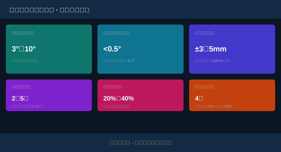
A: All three can hold residual sway angle within 0.5° under design operating conditions, compared with a typical 3°–10° when no anti-sway control is used. The difference lies in the trade-offs: input shaping needs no sensor but requires recalculating pulses whenever the load changes; PID and fuzzy logic control rely on a sway-angle sensor and correct in real time via closed loop. Model predictive control can push residual sway down to the 0.2° range, but demands a high-computing-power controller.
Q: What standards govern positioning accuracy and residual sway angle for electronic anti-sway, and what counts as meeting the standard?
A: Positioning accuracy and residual sway angle are typically written into the project Technical Agreement as acceptance items. Industry-typical figures: standard speed control achieves positioning accuracy of around ±10 mm, electronic anti-sway systems reach ±3–5 mm, and high-precision model predictive control reaches the ±3 mm range. Functional and safety requirements for the control equipment itself can reference ISO 10245, and automation control frameworks can reference ISO 23810.
Q: Roughly how much does it cost to retrofit electronic anti-sway onto an existing European-standard double-girder crane, including modification and calibration?
A: Cost depends on the algorithm approach, whether new sensors are added, and whether the control cabinet is replaced. Sensor-free input shaping solutions cost less; closed-loop solutions run slightly higher due to sensors and tuning; model predictive control is highest because of controller computing power requirements. Specific quotations depend on the scope of retrofit — Kelude Heavy Industry prices each project individually, subject to the actual contract, with no fixed price applied.
Q: How can you tell whether an overhead crane's anti-sway is genuine algorithm-based control or just disguised speed reduction?
A: Check two indicators: whether residual sway angle stays consistently within 0.5° during full-load high-speed travel, and whether the positioning cycle time has been noticeably stretched. True anti-sway keeps speed high while the algorithm cancels out sway; solutions that rely on slowing down will significantly drag out takt time. Run a full-load fast-travel emergency stop test on site and judge by sway angle data rather than visual estimation.
Kelude Heavy Industry specializes in high-end customization of European-standard double-girder cranes from 50 to 300 tons. Anti-sway solutions are matched unit by unit based on positioning accuracy targets, load variation range, and start-stop frequency — not by defaulting to the highest configuration. Algorithm, controller, and sensor are reviewed together at the proposal stage, and accuracy and sway angle targets are written into an acceptance-ready Technical Agreement. Specific configurations are subject to the actual contract.
