

Crane Motor Insulation Resistance Test: 5-Step Megohmmeter Guide
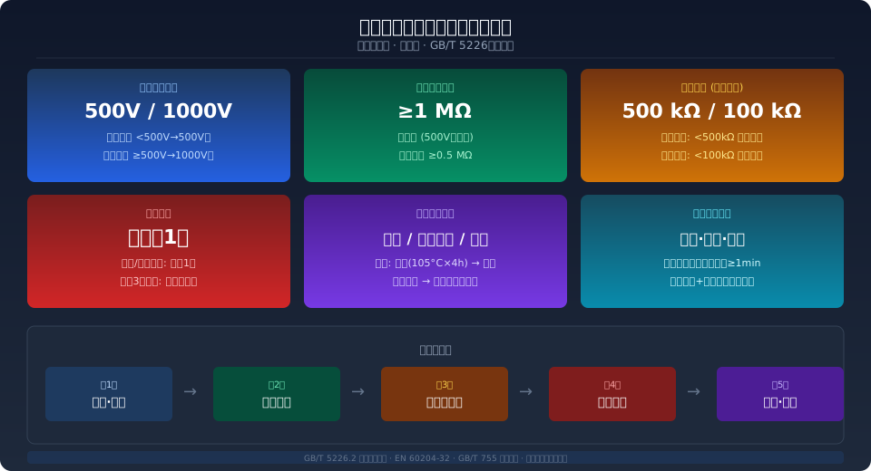
Insulation resistance testing of crane motors is a core electrical safety check. Per IEC 60204-32 and EN 60204-32, a Megohmmeter (Insulation Tester) set to 500V or 1000V is used to measure winding-to-ground and phase-to-phase insulation using a five-step procedure. Acceptance criteria: ≥1 MΩ for main circuits and ≥0.5 MΩ for control circuits, with testing required at least once per quarter.
The electric motor is the heart of a crane — its insulation integrity directly affects operational safety and the risk of electric shock to personnel. Crane motors running in high-temperature, high-humidity, or dusty environments gradually experience insulation aging, moisture absorption, or contamination, which lowers insulation resistance. In severe cases, this can lead to phase-to-phase short circuits, ground faults, or even fire. Kelude Heavy Industry has accumulated extensive insulation testing experience through crane electrical system maintenance. This article provides a complete reference for maintenance personnel, covering the standards behind crane motor insulation resistance testing, Megohmmeter selection, the standard five-step test procedure, and acceptance criteria.
Why Insulation Resistance Testing Matters for Crane Motors
The insulation system of a crane motor endures combined electrical, thermal, and environmental stress during operation. Once winding insulation deteriorates, the consequences go beyond the direct cost of a burned-out motor — it can energize the entire crane structure and create a serious electrocution hazard for operators. Under TSG 51-2023 Crane Safety Technical Supervision Regulation, insulation resistance of the electrical system is a mandatory item in periodic inspections of lifting appliances.
Key standards governing insulation resistance testing include: IEC 60204-32, which specifies minimum acceptable insulation resistance values and test methods for crane electrical equipment; EN 60204-32:2008, which imposes stricter technical requirements for equipment exported to the EU; and IEC 60034 (Rotating Electrical Machines), which defines factory insulation resistance standards and Type Test requirements from the motor manufacturing perspective. For Insulated Bridge Cranes used in special environments such as aluminum smelting plants, additional requirements for ground insulation resistance are specified in JB/T 8907.
Megohmmeter Selection and Pre-Test Preparation
Choosing the right Megohmmeter (Insulation Tester) is the first step toward accurate results. The core selection principle is matching the test voltage to the motor's rated voltage.
Motors rated below 500V — Use a 500V Megohmmeter. This covers most crane Travel Motors (380V supply) and Electric Hoist motors (380V/220V).
Motors rated 500V to 1000V — Use a 1000V Megohmmeter. This applies to 660V or 690V motors used in mining or underground crane applications, as well as certain variable-frequency motors.
Motors rated above 1000V — Use a 2500V Megohmmeter. This is required for 6kV or 10kV high-voltage Hoisting Motors on large Metallurgical Cranes.
Pre-test preparation includes: confirming the motor is de-energized and a "Do Not Operate" lockout tag is placed on the disconnect switch; verifying with a voltage detector that no residual voltage remains on the windings; discharging the windings to ground for at least 1 minute to eliminate capacitive stored energy; cleaning oil and dust from the Junction box; and checking the Megohmmeter battery level and lead integrity. Test personnel must wear insulating gloves and shoes, and work in pairs.
The Five-Step Insulation Resistance Test Procedure
A complete insulation resistance test follows this standardized five-step procedure:
- Step 1: De-Energize and Verify — Open all power supply switches in both the main and control circuits, and place a "Men Working — Do Not Operate" tag on the switch handle. Use a voltage detector rated for the circuit voltage to check each phase and confirm zero residual voltage on the windings before proceeding.
- Step 2: Discharge the Windings — Use a discharge rod (with a current-limiting resistor) to ground each winding for at least 1 minute. For large motors (≥55 kW), extend the discharge time to 3–5 minutes due to higher capacitive stored energy. This step prevents residual charge from damaging the Megohmmeter and protects the tester from electric shock.
- Step 3: Connect the Megohmmeter — Connect the L (Line) terminal to the winding lead under test, and the E (Earth) terminal to the motor frame ground terminal or ground electrode. For high-accuracy measurements where surface leakage current must be eliminated, connect the G (Guard) terminal to a bare copper wire shield wrapped around the insulation surface. Before connecting, verify the Megohmmeter leads are in good condition and do not allow them to twist together.
- Step 4: Test and Read — Crank the Megohmmeter handle at rated speed (typically 120 rpm), or press the test button on an electronic model. After the reading stabilizes, record the 60-second insulation resistance value (R60). Also record the 15-second value (R15) to calculate the polarization index or absorption ratio (R60/R15). A ratio ≥1.3 indicates dry, healthy insulation; a ratio below 1.3 suggests the windings may be moisture-contaminated.
- Step 5: Discharge and Document — After testing, disconnect the Megohmmeter from the winding first, then discharge the winding to ground thoroughly using the discharge rod. Record the results in the motor insulation resistance test log, including: test date, ambient temperature and humidity, Megohmmeter model and voltage setting, phase-to-ground and phase-to-phase resistance values, absorption ratio, test conclusion (Pass/Fail), and tester signature.
Insulation Resistance Acceptance Criteria Quick Reference
Acceptance thresholds vary by voltage class and circuit location. The table below summarizes the pass/fail criteria for common crane motor applications:
| Testing Part | Megohmmeter (Insulation Tester)Position | Acceptance Criteria | Applicable to Motor Type |
|---|---|---|---|
| Main Circuit(power line To Ground) | 500V | ≥1.0 MΩ | 380V Travel Motor, Hoist Motor |
| Control Circuit | 500V | ≥0.5 MΩ | PLC, Contactor Coil, Limit switch Circuit |
| 660VMotor Main Circuit | 1000V | ≥5.0 MΩ | Mining/Underground Dutycrane Motor |
| High Voltage Motor(6kV/10kV) | 2500V | ≥50 MΩ(75°CConverted) | Metallurgical Crane Main Hoisting Motor |
| variable-frequency motor(With Filter) | 1000V | ≥2.0 MΩ | Variable Frequency Speed Control Hoisting / Lifting/Travel Motor |
| Insulated Bridge Crane(Aluminum Electrolysis) | 1000V | ≥20 MΩ | Aluminum Electrolysis Workshop Insulatedcrane |
Note: Insulation resistance is highly temperature-sensitive—for every 10°C rise in temperature, the resistance approximately halves. For accurate assessment, measured values must be corrected to a 75°C reference temperature per ISO 4306 before comparison. New motors typically show insulation resistance ≥50 MΩ (cold state); in-service motors may continue operating as long as readings remain above the acceptance criteria listed in the table above.
Common Causes of Low Insulation Resistance and How to Fix Them
When insulation resistance readings fall below acceptable levels, work through the following three most common root causes:
- Moisture ingress in windings — This is the most frequent cause of insulation degradation, accounting for roughly 60% of all failures. After a motor shuts down, its temperature drops and airborne moisture condenses on the winding surfaces—particularly problematic during humid seasons and in high-humidity workshops (Relative Humidity >85%). Remedy: Place the motor in a drying oven at a constant 105°C for 4–6 hours, or apply the low-voltage short-circuit current method (inject AC at 10%–15% of rated voltage to drive out moisture through self-heating of the windings). Re-test insulation resistance after drying; readings typically return to normal.
- Accumulation of dust and oil contamination — In heavy-dust environments such as foundries and cement grinding rooms, conductive particulates (carbon dust, metal powder) mixed with oil residue build up on winding end turns and inside the junction box, creating leakage paths. Remedy: First blow down winding surfaces with dry compressed air (≤0.4MPa), then spray with an electrical contact cleaner, and finally wipe with a clean lint-free cloth. Allow at least 2 hours of air drying in a ventilated area to ensure complete solvent evaporation before re-testing.
- Aging of insulation materials — Motors operating for extended periods at temperatures exceeding the limits of their Insulation Class will experience thermal aging of the winding varnish and slot insulation paper, resulting in cracking, carbonization, or discoloration. In this case, drying and cleaning will not restore insulation performance. Remedy: Send the motor to a specialized repair facility for vacuum pressure impregnation (VPI) re-varnishing, or replace the stator winding entirely. For motors already in service for more than 10 years or with cumulative operation exceeding 50,000 hours, replacement with a new unit is recommended to avoid repeated downtime from recurring failures.
Online Insulation Monitoring and Preventive Maintenancesulation Monitoring for Predictive Maintenance
Traditional periodic testing leaves blind spots—insulation degradation occurring between scheduled tests goes undetected. For cranes operating at higher Work Duty classifications (A6 to A8), we recommend installing an online Insulation Monitoring Device (IMD) for 24/7 continuous supervision of motor insulation health.
The IMD, mounted inside the main electric control cabinet, injects a low-level DC or low-frequency AC measurement signal into the main circuit and calculates the real-time insulation resistance to ground. A two-stage alarm system is configured: Level 1 Alarm—when insulation resistance drops below 500 kΩ, an audible and visual alarm is triggered in the control room, alerting maintenance personnel to schedule a planned inspection. The equipment may continue operating under this warning condition for no more than 72 hours. Level 2 Alarm—when insulation resistance further drops below 100 kΩ, the protection device automatically cuts off power to the main circuit, forcing a shutdown for immediate repair and eliminating the risk of electric shock or short circuit.
A structured preventive maintenance program is the key to extending motor insulation life. Kelude recommends the following approach: maintain a quarterly insulation resistance test log, plot trend curves of resistance over time, and if readings show a consistent downward trend across three consecutive test cycles (decline >30%), schedule proactive maintenance even if current values remain above the acceptance criteria. For standby motors or cranes that have been idle for more than 3 months, insulation resistance must be verified as acceptable before re-energizing and returning the equipment to service.
Further Reading:
For a complete overview of the standard framework governing crane electrical system design, refer to our interpretation of GB/T 5226.2 – Electrical Safety of Machinery. For cranes exported to the EU, electrical equipment must comply with the insulation testing and technical documentation requirements of EN 60204-32:2008 – Safety of Machinery – Electrical Equipment of Cranes. The overall design and inspection framework should follow the core safety principles outlined in GB/T 3811-2008 – Crane Design Standard and TSG 51-2023 – Crane Safety Technical Supervision Regulation.
Frequently Asked Questions
Q: Does the insulation resistance test on a crane motor require a complete power shutdown? Can it be performed online?
A: Periodic testing with a handheld megohmmeter must be performed only after the equipment has been completely de-energized, verified as safe, and discharged. The 500V to 2500V DC high voltage output from a megohmmeter can damage the IGBT modules in an active VFD or the input circuits of a PLC. Online insulation monitoring devices (IMDs), on the other hand, are specifically designed for live monitoring. They inject a micro-amp level measurement signal (<1mA) into the main circuit without disrupting normal operation. However, the accuracy of an IMD (±15%) is lower than that of a handheld megohmmeter (±5%), and it cannot replace the precise periodic testing performed with a handheld unit. Kelude recommends a combined approach: quarterly precision testing with a handheld megohmmeter supplemented by continuous trend monitoring via an IMD for comprehensive insulation management.
Q: Does a zero insulation resistance reading mean the motor is burnt out?
A: Not necessarily. A zero reading on a megohmmeter can indicate one of two scenarios. First, a true metallic ground fault in the winding, such as direct contact between the copper wire and the iron core after insulation breakdown, which requires rewinding. Second, a low-resistance path caused by water accumulation or severe condensation inside the junction box, which can often be resolved by drying and cleaning. To differentiate: use a multimeter on the resistance (Ω) setting to measure the winding-to-ground resistance. A reading of <10Ω strongly suggests a metallic short circuit. If the multimeter reads >1kΩ but the megohmmeter shows zero, it is typically a false "zero" caused by moisture and should recover after drying.
Q: What special precautions are needed for insulation resistance testing of variable-frequency motors?
A: Before testing a variable-frequency motor, the sine-wave filter or du/dt filter on the VFD output must be completely disconnected from the motor windings. VFD output contains high-frequency voltage pulses (with dv/dt rates reaching 5~10kV/μs), which over time impose additional electrical stress on the first turns of the motor winding, accelerating insulation aging. Consequently, the acceptance criteria for insulation resistance in variable-frequency motors are stricter than for standard mains-frequency motors. For a 380V-class VFD motor, the minimum requirement is ≥2MΩ (as opposed to 1MΩ). Additionally, it is recommended to test the absorption ratio and polarization index (PI=R10min/R1min≥2.0) quarterly as supplementary diagnostic indicators.
Q: How long must insulation resistance test records be retained as per GB/T 5226.2?
A: According to TSG 51, periodic inspection records for lifting appliances, including insulation resistance test data, are considered part of the safety technical file and must be kept for the entire service life of the equipment. In practice, we recommend retaining test logs for at least the last 5 years to establish a trend analysis for insulation degradation. When the equipment is scrapped or transferred, the complete technical file, including all insulation test records, should be handed over. For insulation test reports issued by third-party inspection bodies certified through CMA/CNAS, the retention period must comply with the inspection body's own Quality Management System requirements, which is typically no less than 6 years.
Kelude Heavy Industry has accumulated extensive engineering experience in crane motor selection and insulation testing. Every crane we ship includes a complete electrical system Factory Acceptance Test Report (FAT) with insulation resistance data. We also offer optional online insulation monitoring systems tailored to your needs, ensuring electrical safety management throughout the entire equipment lifecycle. For Technical consultation, call our consultation hotline: 400-086-9590.
