

Gantry Crane Wind Protection: Rail Clamp vs Anchor vs Rail Wedge
One of the most critical safety risks for gantry cranes operating outdoors is sudden wind gusts causing the crane to slide or overturn. Per ISO 4301 Crane Design Standard, anti-wind anti-slip protection is classified into two categories: working-condition protection (rail clamps) and non-working-condition protection (anchor devices + wind-proof wedges). Selection must be based on the crane's lifting capacity, crane rail model, and local wind load classification.
Gantry cranes are the backbone of lifting operations at port terminals, railway freight yards, and steel storage yards. Typhoon season and winter gales are peak periods for safety management every year. If wind protection measures are inadequate, the consequences range from crane slippage damaging the rails to full overturning, causing casualties and property loss. Proper selection and installation of anti-wind anti-slip devices is therefore not just a technical matter—it is a fundamental safety requirement.
This article examines the three mainstream wind protection solutions—rail clamps, anchor devices, and wind-proof wedges—in line with the technical requirements of ISO 4301 Crane Design Standard and TSG 51-2023 Safety Technical Specification for Special Equipment. It provides a systematic overview of each solution's application scope, key parameters, installation specification, and maintenance cycle to support crane operators in their selection process.
Why Gantry Cranes Need Wind Protection
Unlike bridge cranes, a gantry crane's main girder is supported at both ends by rigid and flexible outriggers riding on ground-level crane rails. This configuration results in a higher center of gravity and a significantly larger wind-facing surface area. According to ISO 4301, crane design must account for two wind load scenarios: working condition and non-working condition. The non-working condition wind load corresponds to the maximum wind speed expected once in 50 years at the installation site.
In practice, gantry cranes in coastal regions experience far greater wind loads than those inland. Take, for example, a gantry crane with a 30m span and 50t lifting capacity: under a Force 12 gale (wind speed ≈ 32.6m/s), the horizontal thrust on the wind-facing surface can reach 80–120kN—far exceeding the braking force of the crane travel mechanism's brakes, which typically deliver only 20–40kN. Relying solely on the travel brakes is therefore insufficient for safe stopping in high winds; a dedicated anti-wind anti-slip device is essential.
Three Wind Protection Solutions Compared
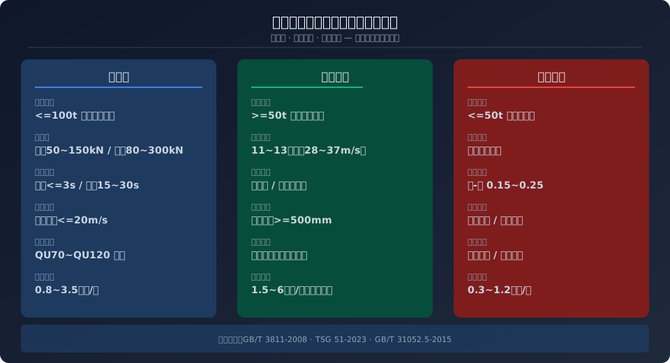
Rail Clamps — Hydraulic or spring mechanisms drive the clamp jaws to grip both sides of the crane rail, using friction to resist wind force. Electric rail clamps offer fast response (under 3 seconds) and stable clamping force (80–300kN), making them suitable for small to medium gantry cranes up to 100t. Manual rail clamps are more economical (approx. $1,200–$3,000 per set) but rely on operator action, with a response time of 15–30 seconds—best suited for sites with sufficient early warning lead time.
During installation, the clearance between the clamp jaws and the rail side must be maintained at 0.5–1.0mm. Once clamped, the jaws must not contact the top surface of the rail.
Anchor Devices — Anchor seats are embedded in the foundation at designated parking positions. When the crane is parked, anchor pins are inserted into the seat holes to achieve mechanical locking. This solution offers the highest wind resistance (capable of withstanding Force 11–13 winds, corresponding to wind speeds of 28–37m/s) and is recommended for medium to large gantry cranes of 50t and above. The foundation embedment must be at least 500mm deep, with concrete strength rated C30 or higher.
Two common configurations exist: manual pin insertion and hydraulic flip-over types. The latter can be operated with a single button from the operator cab but carries a higher cost (approx. $4,400–$8,900 per set, including foundation work). Anchor devices are for non-working condition use only—operating the anchoring mechanism while the crane is in motion is strictly prohibited.
Wind-Proof Wedges — These rely on the friction self-locking principle of a wedge-shaped block inserted between the wheel and the rail to prevent both rotation and sliding. The simplest and most economical option (approx. $400–$1,800 per set), wind-proof wedges suit small gantry cranes up to 50t or serve as supplementary protection on larger units. The steel-on-steel friction coefficient ranges from 0.15 to 0.25, with braking force determined by wedge angle and insertion depth.
Manual hammer-in wedges require physical effort, while spring-loaded automatic versions can be released remotely from the cab. However, spring fatigue over extended use can result in incomplete wedge engagement, so regular inspection of insertion depth is required.
Wind Protection Selection Guide by Crane Type
Based on three key criteria—gantry crane lifting capacity, crane rail model, and site wind conditions—the following combinations offer the most suitable wind protection solutions:
Kelude Heavy Industry: Overhead Crane & Gantry Crane Manufacturer
Kelude Heavy Industry is a professional manufacturer of overhead cranes and gantry cranes, integrating design, manufacturing, installation, and after-sales service. We provide a full range of material handling solutions for industries including steel, metallurgy, mining, and heavy machinery manufacturing.
Complete Crane Product Range for Industrial Applications
Our product lineup covers single-girder and double-girder overhead cranes, gantry cranes, explosion-proof cranes, and low-headroom cranes. Each crane is engineered for reliable performance, easy maintenance, and long service life in demanding environments.
| Crane Type | Typical Applications |
|---|---|
| Single-girder overhead crane | Light to medium duty workshops, warehouses, and maintenance bays |
| Double-girder overhead crane | Heavy-duty production lines, steel yards, and foundries |
| Gantry crane | Outdoor storage yards, precast yards, and container handling |
| Explosion-proof crane | Chemical plants, oil refineries, and other hazardous areas |
Customized Crane Solutions for Heavy-Duty Handling
We understand that every operation is unique. Our engineering team works closely with you to design cranes that match your specific load capacity, span, lifting height, and duty cycle requirements. From a single crane to a complete material handling system, we deliver solutions that improve productivity and safety.
Quality Assurance and International Standards Compliance
All our cranes are manufactured in strict accordance with ISO 4301 for crane classification, ISO 12480 for safe use, and IEC 60204-32 for electrical equipment. Every crane undergoes rigorous testing and inspection before delivery, ensuring compliance with international safety and performance standards.
Global Export and After-Sales Support
With years of export experience, we supply cranes to markets across the United States, Europe, and Southeast Asia. Our team provides complete documentation, installation guidance, and responsive after-sales support to ensure smooth operation from day one.
Frequently Asked Questions
Q: What is your lead time for a standard overhead crane?
A: Typical lead time for a standard single-girder crane is 30–45 days after design approval. Double-girder and custom-engineered cranes may require 60–90 days depending on complexity.
Q: Do you provide installation supervision?
A: Yes, we offer on-site installation supervision and operator training. Remote technical support is also available throughout the installation process.
Q: Can you customize cranes for explosion-proof environments?
A: Absolutely. We supply explosion-proof cranes with appropriate motor and electrical protection ratings, designed for hazardous areas classified under international standards.
Q: What is your warranty policy?
A: We provide a 12-month warranty covering manufacturing defects and workmanship. Extended warranty and maintenance contracts are available upon request.
| crane Rated Capacity | Recommended Anti-Wind Scheme | working condition Protection | non-working condition Protection | Applicable Wind Speed Range |
|---|---|---|---|---|
| Not Exceeding20t Light Duty Gantry Crane | Electric Rail Clamp + wind-proof wedge | Electric Rail Clamp(Clamping Force50~100kN) | Spring Automatic Rail Wedge(Per Wheel1Set(s)) | Not Exceeding20m/s(8Class and Below) |
| 20~50t Medium Duty Gantry Crane | Electric Rail Clamp + Anchor device | Electric Rail Clamp(Clamping Force100~200kN) | Manual Pin-Type Anchoring(4Unit(s)Outrigger Each1Set(s)) | Not Exceeding25m/s(10Class and Below) |
| 50~100t Heavy Duty Gantry Crane | Electric Rail Clamp + Hydraulic Pin-Type Anchoring | Electric Rail Clamp(Clamping Force200~300kN) | Hydraulic Tilt-Up Anchoring(Remote Control) | Not Exceeding30m/s(11Class and Below) |
| Not Less Than100t Super Heavy Duty Gantry Crane | Hydraulic Rail Clamp + Hydraulic Pin-Type Anchoring + Rail Wedge | Hydraulic Rail Clamp(Clamping Force Not Less Than300kN) | Hydraulic Pin-Type Anchoring + Rail Wedge Dual Locking | Not Exceeding37m/s(13Class and Below) |
| Coastal/All Capacities in Typhoon-Prone Areas | Electric Rail Clamp + Pin-Type Anchoring + Rail Wedge | Electric Rail Clamp(Fully automatic Interlock) | Triple Protection(Pin-Type Anchoring+Rail Wedge+Ground Anchor Tie-Down Cable) | Not Exceeding45m/s(14Classand Above) |
Installation Guidelines for Wind Protection Systems
Rail Clamp Installation — The rail clamp base is secured to the bottom of the crane end carriage using bolts or welding. The centerline of the clamp jaws must align with the centerline of the crane rail, with a maximum allowable deviation of ±2 mm. After installation, a clamping force test must be performed: use a dynamometer to measure the actual clamping force exerted by the jaws on the rail, which should be within ±10% of the design value.
For electrical interlock, the rail clamp must be interlocked with the crane travel mechanism — the crane bridge cannot start unless the rail clamp is fully released, and the rail clamp must not engage while the crane bridge is in motion.
Anchor Device Installation — Anchor seats are embedded during the foundation construction of the gantry crane rail track, requiring high positioning accuracy: the center-to-center distance deviation between adjacent anchor seats must not exceed ±3 mm, and the height difference between the top of the anchor seat and the top of the rail must not exceed 2 mm. The clearance between the anchor pin and the anchor seat hole should be 1–2 mm — too tight a fit makes insertion and removal difficult, while too loose a fit can create impact loads during high winds. Hydraulic flip-type anchor devices require a dedicated hydraulic pump station, which should ideally be mounted on the inside of the crane end carriage to protect it from sun and rain exposure.
Wind-Proof Wedge Installation — Rail wedges are installed on the crane rail in front of and behind the crane bridge wheels. Each wedge is connected to the crane frame via a chain or wire rope to prevent loss. Spring-operated automatic wedges use an electromagnetic release mechanism and must be electrically interlocked with the crane travel mechanism. During installation, the included angle between the wedge and the top surface of the rail should be 7 to 10 degrees, with a minimum wedging depth of 80 mm. Over extended service, wear pitting may develop on the rail head surface; regular grinding and dressing are required to maintain a smooth contact surface between the wedge and the rail.
Electrical Control System — Status signals from all wind protection devices (clamped/released, anchor inserted/withdrawn, wedge engaged/stowed) should be wired into the crane PLC control system and displayed in real time on the touch screen (HMI) in the operator cab. An anemometer interlock function is recommended: when the anemometer detects wind speeds exceeding the preset warning threshold (e.g., 15 m/s), the system automatically triggers an audible and visual alarm and activates the rail clamp; when wind speeds continue to rise to a dangerous level (e.g., 25 m/s), the system automatically triggers the release signal for the anchor device and rail wedges.
Maintenance and Inspection Intervals
The reliability of the anti-wind anti-slip device depends heavily on regular maintenance and inspection. In accordance with TSG 51-2023 Crane Safety Technical Supervision Regulation, the gantry crane user unit must establish a dedicated inspection log for wind protection devices, clearly defining inspection items, intervals, and responsible personnel.
| Inspection Item | Inspection Method | Acceptance Criteria | Inspection Interval |
|---|---|---|---|
| Rail clamp Jaw Clearance | Feeler Gauge Measurement of Jaw-to-Crane Rail Side Clearance | 0.5~1.0mm(Uniform Contact) | Monthly |
| Clamping Force Testing | Hydraulic On-Site Dynamometer Calibration | Not Less Than Design Value80% | Semi-Annually |
| anchor pin Fit Clearance | optical flat Measurement of Pin-to-Housing Bore Clearance | 1~2mm(No Corrosion Binding) | Quarterly |
| Rail Wedge Wear Measurement | optical flat Measurement of Wedge Thickness | Wear Not Exceeding Original Thickness20% | Monthly |
| Electrical Interlock Function | Simulated Signal Triggering of Interlock Testing | Interlock Activation Correct, Nolatency | Quarterly |
| Anemometer Calibration | Standard Wind Speed Source Comparison Calibration | Deviation Within ±1m/s | Annually |
In addition to the periodic inspections mentioned above, a quick functional check should be performed before each high-wind warning:
- Verify that the rail clamp closes properly.
- Confirm that the anchor pin is free from corrosion and binding.
- Ensure the rail wedge releases freely.
During typhoon season, it is recommended to upgrade the monthly inspection to a weekly one, with sign-off by the safety supervisor. Kelude has accumulated extensive experience in maintaining wind protection devices across multiple coastal projects and can provide customers with customized inspection plans and spare parts supply.
Related Reading:
· ISO 9927-8:2016 — Interpretation of Inspection Procedures for Gantry Cranes
· How to Match Span and Overhang for Gantry Cranes
· Synchronous Control Principle and Tuning for Gantry Crane Bridge Travel
· Outdoor Rain and Corrosion Protection Solutions for Gantry Cranes
FAQ
Q: What are the mandatory requirements for wind protection devices on gantry cranes under ISO 4301?
A: ISO 4301 explicitly requires that outdoor cranes be equipped with anti-wind anti-slip devices, with separate provisions for working and non-working conditions. In the working condition, the rail clamp or brake must resist wind loads up to 20 m/s. In the non-working condition, the anchor device or rail wedge must ensure the crane does not slide under the maximum wind speed expected once in 50 years. The standard also mandates electrical interlocking between the wind protection device and the crane travel mechanism.
Q: How many layers of wind protection are recommended for gantry cranes in typhoon-prone coastal areas?
A: For typhoon-prone coastal regions (e.g., Guangdong, Fujian, and Zhejiang coastlines), a three-tier protection system is recommended: electric rail clamp (for working condition) + hydraulic anchor device (primary protection for non-working condition) + wind-proof wedge (auxiliary protection) + ground anchor tie-downs (additional reinforcement for extreme weather). The ground anchor tie-downs use wire rope with a diameter of 20 mm or above, secured at one end to the anchor point at the base of the gantry crane outrigger and at the other end to pre-embedded ground anchor piles, providing an additional 80–120 kN of holding force.
Q: At what level of jaw wear must the rail clamp be replaced?
A: The jaw lining of the rail clamp (typically made of high-hardness alloy steel or composite material) must be replaced when wear exceeds 30% of the original thickness. Worn jaws reduce the contact area with the crane rail, leading to a decrease in actual clamping force. When a feeler gauge detects a gap of more than 2.0 mm between the jaw and the rail side (standard: 0.5–1.0 mm), the jaw lining should be replaced even if single-side clamping force still meets the requirement, to ensure uniform contact on both sides.
Q: What are the key parameters for the foundation construction of a gantry crane anchor device?
A: The anchor foundation is cast with C30 or higher strength concrete. The center distance deviation of the pre-embedded anchor seat must be controlled within ±3 mm, and the height difference between the top surface of the anchor seat and the top of the crane rail must not exceed 2 mm. Foundation dimensions are determined by the crane capacity: for a 50 t gantry crane, the recommended anchor foundation size is 800 × 800 × 600 mm (length × width × depth); for 100 t and above, 1200 × 1200 × 800 mm is recommended. The foundation must be cured for at least 28 days before being put into service.
Kelude is committed to full-life-cycle safety solutions for gantry cranes, offering one-stop technical services for anti-wind anti-slip devices — from selection consultation and custom design to installation & commissioning and periodic inspection. Consultation hotline: 400-086-9590
