

Overhead Crane Brake Online Monitoring Technical Solution
Overhead crane brake online detection uses laser sensors and infrared temperature sensors to monitor wear and temperature in real time, with AI predicting degradation trends to replace traditional manual inspection.
Overhead crane brakes are safety-critical components—not something you fix after they fail, but something that must never fail in the first place. A hoisting brake malfunction ranks among the most severe types of crane accidents. Yet most factories still rely on periodic gap adjustments and listening for unusual sounds—maintenance practices that depend entirely on the technician's experience. The same brake can end up with clearance settings that vary by as much as 0.3 mm between different technicians, which has a significant impact on braking performance.
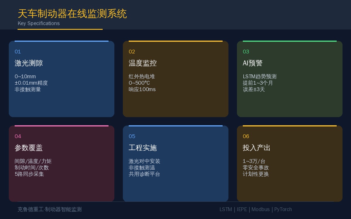
Online brake monitoring uses laser displacement sensors to measure brake clearance, thermocouples to track brake disc temperature, and AI models to analyze degradation trends. The sensors are all externally mounted, so the brake's original structure and safety systems remain untouched. A complete brake monitoring system—including sensors and data acquisition units—costs approximately $1,500 to $4,500 per unit, covering both dynamic braking and static brake applications.
Brake Monitoring Parameters and Sensor Selection
| Detection Parameter | Sensor Type | Measuring Range/Accuracy | Mounting Position |
|---|---|---|---|
| Brake Clearance | laser displacement sensor | 0~10mm / ±0.01mm | Brake Arm Between Armature and |
| Brake Lining Thickness | Hall Effect Proximity Switch / Inductive Sensor/Eddy Current Sensor | 0~20mm / ±0.05mm | Brake Lining Back Plate Rear |
| Brake Disc / Brake Rotor Temperature | Infrared Thermopile/Thermocouple | 0~500°C / ±1.5°C | Brake Disc / Brake Rotor Proximity 50mm |
| Braking Time | Photoelectric Sensor+PLCTiming | 0~5s / ±10ms | Motor Shaft End + Control Cabinet |
| Braking torque | Strain Gaugeforce sensor | 0~500Nm / ±1% | Brake Arm Push Rod Location |
Brake Clearance and Lining Wear: How They Correlate
Brake clearance—the gap between the friction lining and the brake disc when the brake is released—is the primary maintenance indicator for overhead crane brakes. Standard clearance typically ranges from 0.5 to 1.5 mm, depending on the brake model and braking torque. Excessive clearance compromises braking torque, while insufficient clearance accelerates friction lining wear and can cause drag braking and overheating if the brake fails to fully release.
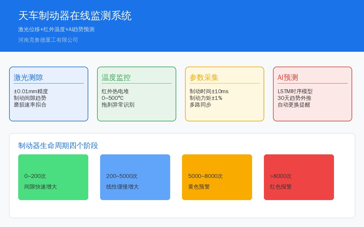
Brake clearance follows a predictable evolution pattern. After new friction linings are installed, clearance increases rapidly during the first 100–200 braking cycles as the linings seat in. A stable period follows, during which clearance grows slowly at roughly 0.01–0.03 mm per 1,000 braking cycles. Once the friction lining wears down to its minimum thickness—typically 30–40% of the original—clearance begins to accelerate sharply. By continuously tracking the clearance curve with a laser displacement sensor, an AI model can calculate the wear rate and forecast when the lining will reach its limit 1–3 months in advance.
| Phase | Braking Cycle Count | Gap Change Rate | AIPre-Alarm |
|---|---|---|---|
| Break-in Period | 0~200Cycles | Rapid Increase(0.05~0.1mm/Hundreds of Cycles) | — |
| Stable Period | 200~5000Cycles | Slow Linear Increase(0.01~0.03mm/Thousands of Cycles) | — |
| Acceleration Wear Break-in Period | 5000~8000Cycles | Accelerated Gap Increase, Rate Doubling | Yellow Alarm |
| End-of-Life Period | 8000~10000Cycles | Gap>2.0mm, bow shackle Nearly Worn Out | Red Alarm |
Brake Disc Temperature Monitoring
Brake disc temperature is a key indicator of brake performance. Under normal braking conditions, the disc temperature typically ranges from 80 to 150°C, depending on braking frequency and load. The AI model automatically flags the following abnormal patterns:
| Abnormal Mode | Temperature Signature | Possible Cause | Recommended Action |
|---|---|---|---|
| Sustained High Temperature | >200°CPersistent | Brake Drag Braking/Insufficient Gap | Stop and Inspect Gap and Hydraulic Power Unit |
| Rapid Temperature Rise | Single Event Braking Temperature Rise>100°C | Brake Lining Surface Hardening/Slippage | Inspect Friction lining Surface Condition |
| Temperature Drop Instead of Rise | Frequent Braking But<50°C | Sensor Fault or Brake Not Engaged | Inspect Sensor Stop and Inspect Gap and Brake Actuation |
AI Trend Analysis for Brake Degradation
Rather than making a binary "good/bad" judgment, the AI model evaluates trends. Brake clearance, temperature, and braking time signals feed into an LSTM time-series model, which outputs a 30-day brake clearance prediction curve along with the probability of reaching the limit value. The core logic:
# Brake Clearance Trend Prediction(LSTM) import numpy as np from tensorflow.keras.models import Sequential from tensorflow.keras.layers import LSTM, Dense # Input: Historical30Day Brake Clearance+Temperature+Braking Time # Output: Future30Day Clearance Prediction Value model = Sequential([ LSTM(64, input_shape=(30, 3), return_sequences=True), LSTM(32), Dense(30) # Predict Future30Days ]) model.compile(loss='mse', optimizer='adam') # Brake Clearance Trend Prediction history = np.array([/* Historical30Day Data */]) pred = model.predict(history.reshape(1, 30, 3))[0] # Predict Threshold Exceedance Time2.0mm days_to_alarm = np.argmax(pred > 2.0) print(f"Estimated {days_to_alarm} Days Until Friction Lining Replacement Required")Key Engineering Implementation Considerations
1. Laser sensor installation accuracy is critical. With brake clearance ranging from 0.5 to 1.5 mm, the laser displacement sensor must maintain a measurement error below 0.01 mm. The sensor beam must be perfectly perpendicular to the armature surface during installation—a tilt angle exceeding 5° will push measurement error past 0.02 mm. A laser alignment tool is recommended for installation assistance.
2. Use non-contact temperature sensing. Since the brake disc is a rotating component, contact thermocouples are not viable. An infrared thermopile sensor offers a response time of approximately 100 ms, with a measurement spot diameter of about 10 mm at a 50 mm working distance—simply aim it at the brake disc friction zone. Be sure to protect the sensor from water and oil ingress, as oil contamination on the infrared sensor window will cause low readings.
3. Share the monitoring platform between brake and motor diagnostics. The brake mounts on the motor shaft end, so both sensor sets can feed into the same industrial PC and data acquisition system. A unified deployment is recommended, cutting hardware costs by roughly 30%.
4. The baseline learning period must cover the full operating envelope. Brake clearance differs between no-load and full-load conditions (elastic deformation accounts for a variation of approximately 0.03–0.05 mm). The system requires at least one week of data collection to learn the normal clearance range under varying loads.
Frequently Asked Questions
Conclusion
The true value of online brake monitoring lies not in detection but in prediction. The brake clearance trend captured by the laser displacement sensor can forecast friction lining replacement 1 to 3 months in advance, shifting maintenance from emergency repair to planned replacement. We deployed the monitoring system on 8 brakes in the overhead crane workshop of a steel mill, achieving zero brake-related safety incidents over a full year of operation, with all friction lining replacements executed on schedule.
