

AI Vision Crane Wire Rope Inspection: Broken Wire & Wear Detection
AI Vision–Based Online Wire Rope Inspection for Overhead Cranes replaces manual visual checks by automatically detecting broken wires, wear, and corrosion using deep-learning visual recognition.
The wire rope is the core load-bearing component of an overhead crane's hoisting system, and it is also a wear part that must be periodically retired as required by regulation. According to GB/T 5972-2023 Wire Rope Maintenance, Inspection, and Retirement for Cranes, the rope must be taken out of service when the number of broken wires within one rope lay reaches 10% of the total wire count. However, manual visual inspection is inefficient—for a 30-meter rope, an inspector needs at least 20 minutes to walk the full length, and working at height carries significant safety risks. The bigger problem: internal broken wires and corrosion are invisible from the outside, and by the time they become visible to the naked eye, the rope has already reached its retirement threshold.
Two main wire rope inspection technologies are available today: electromagnetic leakage flux (LF) testing and AI vision inspection. Electromagnetic methods can detect internal broken wires and loss of cross-sectional area, but the equipment is expensive (roughly $4,400–$14,800 per unit), demands highly skilled operators, and cannot distinguish between broken wires and localized wear. AI vision inspection uses industrial cameras to capture surface images of the rope and applies deep learning to identify broken wires, wear, corrosion, and deformation—at a lower equipment cost (about $1,500–$4,400 per unit), with simple operation and results that are immediately visible.
The two approaches are actually complementary—we covered the electromagnetic method in detail in our earlier article on online crane wire rope inspection technology: electromagnetic testing provides 100% full-coverage screening (once or twice a year), while AI vision delivers high-frequency online monitoring (weekly). This article covers the complete engineering implementation of the AI vision approach.
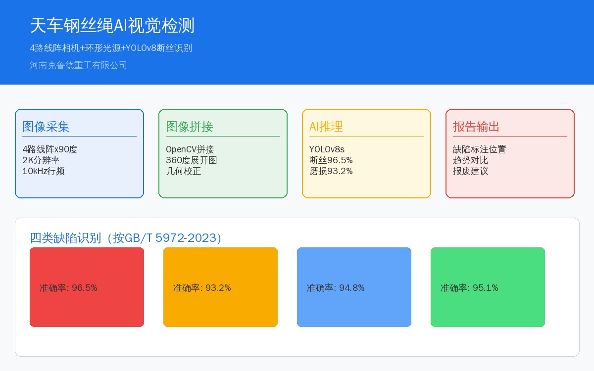
System Architecture for AI Wire Rope Inspection
| Module | Function | Technical Solution |
|---|---|---|
| Image Acquisition | 360°Orbital Capture Wire Rope Surface | 4Linear Array Camera+Ring LEDLight Source |
| Image Stitching | 4Route Image Stitching into Panoramic Unfolded View | Open CVImage Stitching+Geometric Correction |
| AIInference | Wire Break/Wear/Corrosion/Deformation Classification | YOLOv8s+Tensor RT |
| Report Output | Detection Recording+Trend Analysis+Scrap Recommendation | PDFReport+Database Archiving |
Camera and Lighting Configuration for Wire Rope Inspection
One of the key challenges in AI-based visual inspection of wire ropes is their cylindrical geometry. Since the rope surface is composed of multiple strands, a single camera shot can only capture half of the circumference. To overcome this, four line scan cameras are positioned at 90° intervals around the rope, synchronized by an encoder trigger for simultaneous image acquisition. Each rope is scanned along its full circumference and the images are stitched into a panoramic unwrapped view.
Camera parameters: 2K line scan resolution (2048 pixels), 7μm pixel size, and a line rate of 10kHz, which delivers a longitudinal resolution of 0.05mm per line at a rope speed of 0.5m/s. A ring-shaped LED light source (white light, 6500K color temperature) is mounted in front of the cameras to provide 360° uniform illumination. Both the cameras and lighting are enclosed in an aluminum alloy protective cover rated IP65, installed on the vertical section of the wire rope near the hoisting mechanism of the overhead crane.
| Parameter | Value | Description |
|---|---|---|
| Camera Type | Linear Array CMOS | 4Unit90°Circumferential Arrangement |
| Resolution | 2K (2048×1) | Pixel7μm |
| Line Rate | 10kHz | Coordination Encoder Triggering |
| Illumination | Ring LEDWhite Light | 360°Uniform Illumination |
| Detection Start Button | 0.3~0.5m/s | overhead crane Lifting Speedof50% |
| minimum Detectable | 0.2mm Wire Break | Single Wire Diameter |
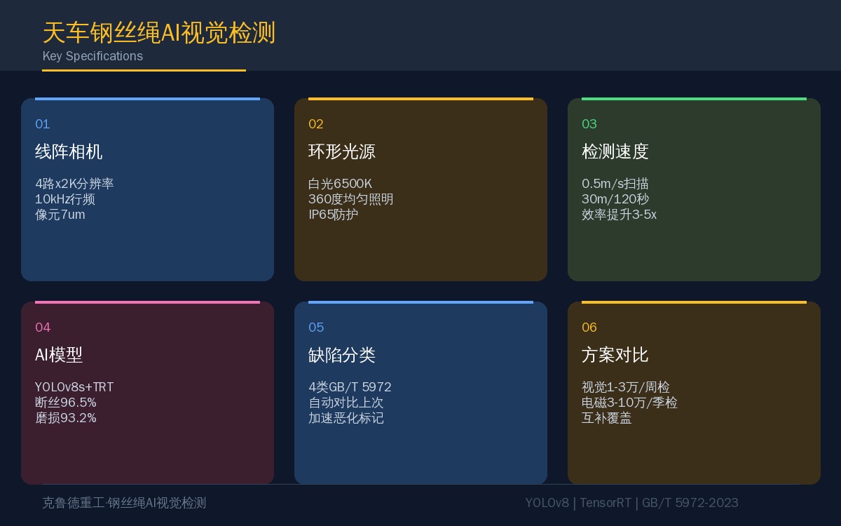
AI Model Architecture and Defect Classification
The system runs on a YOLOv8s model and classifies defects in accordance with ISO 4309:2023.
| Defect Camera Type | Visual Feature | AIAccuracy | Scrap Standard(GB/T 5972-2016) |
|---|---|---|---|
| Wire Break | Wire End Lifting or Fracture Gap | 96.5% | Within One Lay Length≥10%Total Wire Count |
| Wear | Surface Polished and Bright, Local Diameter Reduction | 93.2% | Diameter reduction≥7%Wire End Lifting or Wear≥40%Cross-Section |
| Corrosion | Surface Rust Spots/Pitting/Color Change | 94.8% | Surface Corrosion Pitting or Corrosion Penetrating Internally |
| Deformation | Lantern Shape/Kinking/Flattening/Bending | 95.1% | Obvious Deformation Immediate Scrap |
Online Wire Rope Inspection Process
The inspection procedure begins with the crane in a stopped state. The wire rope inspection device is clamped onto the rope near the hoisting end, and the hoisting mechanism is jogged at a speed of 0.3–0.5 m/s. A line-scan camera captures continuous images while an encoder triggers line exposure every 0.05 mm. A 30-meter wire rope is fully scanned in approximately 120 seconds. Once the scan is complete, the AI automatically generates a report flagging the location, type, and confidence level of every detected defect.
Results are automatically compared against the previous inspection. If the number of broken wires has increased—say, from 3 to 5—the system flags the rope as "Watch — Accelerating Deterioration," even if it has not yet reached the discard threshold.
Key Engineering Considerations for Implementation
1. Oil contamination on the rope surface is the biggest interference factor. Crane wire ropes are lubricated, and the resulting oil film reflects light, degrading image quality. Solution: install a ring-shaped air nozzle in front of the camera (compressed air at 0.3–0.5 MPa) to blow off excess oil film from the rope surface during imaging. The nozzle should be angled at approximately 45° rather than pointing directly at the camera window—otherwise, oil mist can be blown onto the lens.
2. Distinguishing strand texture from broken wires. The interwoven strand pattern on a normal rope surface can resemble broken wires—especially at worn strand edges—and this is the most common source of AI misclassification. During training, include at least 30% "hard negative samples" (image regions that look like broken wires but are actually normal texture) to improve the model's ability to discriminate between the two.
3. Calibrate regularly with a reference rope. Prepare a calibration wire rope with known defects (containing artificially created standard broken wires, wear, and corrosion). Run the calibration rope through the system before each inspection session to confirm the AI's detection results match the known reference before proceeding with actual inspections.
4. Combine electromagnetic and visual methods. AI vision detects surface conditions; electromagnetic testing detects internal conditions. Recommended cadence: weekly AI vision inspections (for surface broken wires and wear) plus quarterly electromagnetic testing (for internal broken wires and cross-sectional area loss). When visual inspection flags an anomaly, schedule electromagnetic testing immediately to verify internal conditions.
Frequently Asked Questions
Conclusion
Wire rope inspection is not optional—ISO 4309 is a mandatory standard, and failure to conduct inspections on schedule can result in liability if an accident occurs. AI vision inspection transforms wire rope inspection from "climbing onto the crane for a visual check" to "mounting the device, jogging the hoist for two minutes, and getting a report." With equipment costs ranging from $10,000 to $30,000 per unit and a single wire rope priced between $450 and $1,200, saving just one rope from premature retirement due to undetected deterioration pays for the equipment.
