

Overhead Crane 5G & WiFi 6 Networks: PROFINET Guide
Industrial Communication Networks for Overhead Cranes: 5G Private Networks, Wi-Fi 6, and PROFINET Real-Time Engineering Practice. The industrial communication network of an overhead crane serves as the information backbone of the intelligent control system—it carries PROFINET real-time motion control data (10 ms cycle), OPC UA equipment status acquisition data, 5G/Wi-Fi 6 wireless remote control data, and real-time video surveillance streams.
The industrial communication network of an overhead crane is the information backbone of its intelligent control system. It carries PROFINET real-time motion control data (10 ms cycle), OPC UA equipment status acquisition, 5G/Wi-Fi 6 wireless remote control signals, and video surveillance streams. In its smart factory crane projects, Kelude has deployed a three-tier communication architecture that integrates a PROFINET RT industrial Ethernet ring, a 5G URLLC private network, and Wi-Fi 6 wireless coverage. This architecture meets the differentiated demands of crane control—hard real-time performance at a 10 ms cycle, wireless remote control latency below 5 ms ms, and video stream bandwidth exceeding 100 Mbps. This article provides a systematic account of this engineering practice, covering network topology design, communication protocol configuration, wireless coverage optimization, and network management platforms.
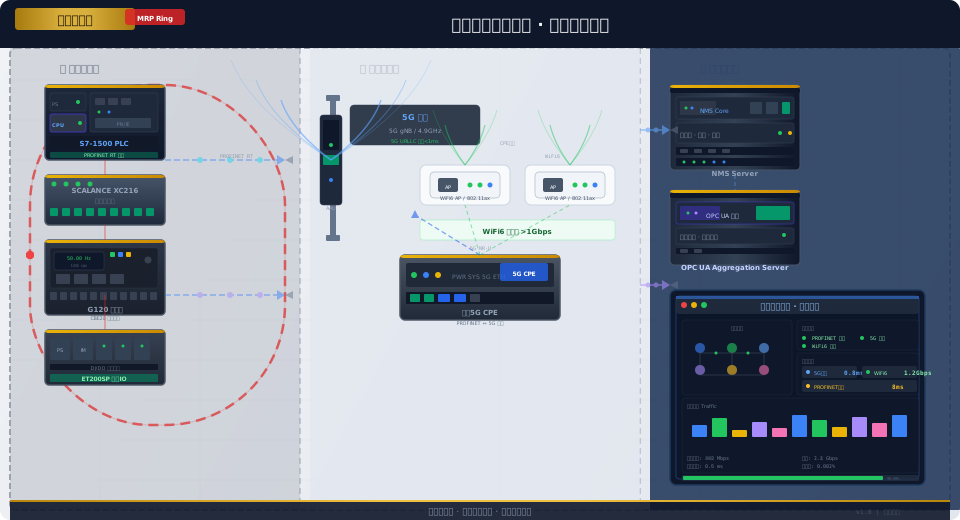
Overhead Crane Communication Network Architecture Overview
The communication network in a smart crane factory must simultaneously carry three distinct types of data traffic. Control-layer traffic includes PROFINET RT cyclic I/O data (PLC to VFD to remote I/O, 10 ms cycle) and PROFIsafe safety data (20 ms cycle). This traffic demands the highest real-time performance, uses small data packets (approximately 40 to 200 bytes per I/O message), and operates in a cyclic polling mode between controllers and devices. Monitoring-layer traffic includes OPC UA subscription data (PLC to edge gateway to MES/SCADA, 50 ms to 1 s cycle) and Modbus TCP polling data (SCADA to PLC, 100 ms to 1 s cycle). Data packets are medium-sized (200 to 1,000 bytes) and some jitter is tolerable. Information-layer traffic includes MQTT cloud platform data, video surveillance streams (one 1080p camera per crane, approximately 4 to 8 Mbps per stream), remote control data, and Digital Twin synchronization data. This layer consumes the most bandwidth but has the lowest real-time requirements.
| Communication Technology | Latency | Bandwidth | Coverage Range | Application Scenarios |
|---|---|---|---|---|
| PROFINET RT | Less Than1ms | 100Mbps | 100m/Segment | PLCTo Frequency Inverter / VFDTo IOStation Control Layer |
| 5G URLLC | Less Than1ms | Uplink100Mbps | 500To1000m | Remote Control+Video Return |
| Wi Fi6 | Less Than5ms | 1.2Gbps | 50To100m/AP | Inspection Robot/Mobile Terminal |
| OPC UA | 5To50ms | — | Cross-Segment | Upper System Data Integration |
Kelude Heavy Industry's standard overhead crane workshop communication network uses a three-tier topology. The bottom tier is a PROFINET RT industrial Ethernet ring (MRP Ring) that connects the S7-1500 PLC, G120 VFDs, and ET200SP remote I/O stations inside each crane control cabinet. The ring is formed using SCALANCE XC216 managed switches, with a ring recovery time of less than 200 ms. The middle tier provides wireless coverage, including a 5G private network small cell (covering the entire workshop and offering a URLLC slice for remote crane operation) and a cluster of Wi-Fi 6 access points (covering maintenance and administrative areas for high-bandwidth access). The top tier is the workshop-level network management layer, which uses an OPC UA aggregation server to model the data from the bottom tier and publish it to the MES and SCADA systems.
PROFINET RT and MRP Ring for Crane Control
PROFINET RT is the foundational communication protocol for crane motion control, transmitting cyclic I/O data between the S7-1500 PLC, G120 VFDs, and ET200SP remote I/O stations. The PROFINET RT communication cycle is set to 10 ms, matching the VFD speed loop refresh rate and the execution cycle of the motion control function blocks. During each I/O cycle, the PLC writes the target rotational speed, torque limit, and control word to the VFD's output process data (Output PZD). The VFD writes its actual speed, current, and status word to the input process data (Input PZD). Each PZD channel has a data length of 16 bytes (8 words of 16 bits).
The network topology uses MRP (Media Redundancy Protocol) to create a redundant ring—all PROFINET IO devices are connected in a ring topology via SCALANCE XC216 switches. During normal operation, the Ring Manager (one of the SCALANCE XC216 switches) blocks one logical port on the ring to prevent broadcast storms, and data travels in one direction around the ring. If a physical link failure occurs anywhere in the ring, the Ring Manager automatically switches the blocking port within 200 ms, allowing data to reach its destination by traveling in the other direction, ensuring uninterrupted communication. This MRP ring redundancy meets the SIL3 safety communication requirement for network availability of no less than 99.99%, ensuring that a single point of link failure does not affect crane operation.
For PROFINET IO device configuration, each crane is equipped with a SCALANCE XC216 switch as a ring node. The XC216 provides 16 10/100/1000 Mbps auto-negotiating RJ45 ports (including 2 Gigabit SFP fiber ports) and supports PROFINET Conformance Class B (RT) and CC-C (IRT). The PLC connects to port 1 of the XC216, the G120 VFD to port 2, and the ET200SP to port 3. Four ports are reserved for future expansion (e.g., encoder interface modules, HMI, edge gateway). Ports 15 and 16 of the XC216 are configured as MRP ring ports, connecting to the XC216 switches in adjacent crane control cabinets. The MRP roles for each XC216 in the ring are configured as follows: one crane's XC216 is set as the Ring Manager (RM), and the others are set as Ring Clients (RC). The RM is responsible for ring fault detection and recovery, while the RCs are responsible for forwarding data.
Installation and wiring requirements: PROFINET cables must be CAT6A shielded industrial Ethernet cables (S/FTP, AWG22/1). IP65 industrial RJ45 connectors should be fitted to both ends of the cables. Inside the control cabinet, cables should be routed along metal cable trays, maintaining a minimum distance of 300 mm from VFD power cables. For the ring fiber optic cable crossing the crane rails, single-mode OS2 fiber (9/125 µm) with Gigabit SFP optical modules is required. The fiber optic cable should be laid along the cable tray on the crane rail, with 20% spare length reserved. The maximum length for a single segment of PROFINET copper cable is 100 m; for longer distances, cascade via the Gigabit fiber ports on the XC216.
5G Private Network Deployment for Remote Crane Operation
The 5G private network is key infrastructure for remote crane control and video feedback. In its smart crane factory, Kelude Heavy Industry has deployed a 5G standalone (SA) private network operating in the 4.9 GHz band (China's industrial 5GDedicated Frequency Band). The core network uses a local User Plane Function (UPF) deployment with Multi-access Edge Computing (MEC). Control plane signaling is handled by the operator's core network, while user plane data terminates at the on-site UPF. This architecture keeps end-to-end latency within 5 ms, meeting the ultra-reliable low-latency communication (URLLC) requirements for remote crane operation.
The 5G private network equipment deployment plan is as follows. 5G small cells (gNB Distributed Units) are installed on the workshop ceiling or crane runway girder columns. Each small cell provides a coverage radius of approximately 100 m. Two small cells are deployed per standard workshop (100 m × 30 m) to ensure seamless coverage. The small cells connect via fronthaul fiber to a Central Unit (gNB CU) and the UPF, which are co-located in the equipment room. The CU and UPF share a standard 19-inch server (Intel Xeon 16-core processor, 64 GB RAM, 2 × 10 Gbps fiber NICs). A Customer Premises Equipment (CPE) unit is installed inside the crane control cabinet and connects to the crane PLC and cameras via Gigabit Ethernet ports. The 5G CPE is an industrial-grade outdoor unit (Protection Rating IP65, wide temperature range -30°C to 65°C). Its antenna is routed via a feeder cable to an omnidirectional antenna on top of the control cabinet.
5G URLLC slice configuration: A dedicated URLLC slice is created in the Network Slice Management Function (NSMF) of the 5G core network. The slice identifier SST=2 (URLLC) is used. Low-latency uplink scheduling parameters are configured: mini-slot scheduling period (2 OFDM symbols, approximately 0.14 ms), pre-scheduling period of 1 ms, and a maximum of 2 HARQ retransmissions (to reduce retransmission latency). Field tests show that the end-to-end latency under the URLLC slice (CPE to gNB to UPF to remote console) is consistently between 1.5 ms and 3 ms, with jitter under 0.5 ms. This meets the strict requirement of latency under 10 ms for remote crane operation. The measured uplink bandwidth for a single CPE under the URLLC slice is approximately 80 Mbps, which can simultaneously support one 1080P video stream (8 Mbps) and the remote control command stream (10 Kbps), providing ample bandwidth.
Wi-Fi 6 Coverage and Roaming Optimization in Workshop
Wi-Fi 6 (802.11ax) serves two communication roles in the crane workshop. The first is high-bandwidth data backhaul for ground inspection robots. These robots are equipped with HD cameras and sensor arrays, generating approximately 2 GB of inspection data per hour (including 4K video, thermal imaging, and vibration waveforms). Wi-Fi 6's OFDMA multi-user scheduling and MU-MIMO uplink technologies provide effective uplink throughput greater than 500 Mbps. The second role is network access for mobile devices (tablets/smartphones) in the workshop. Maintenance personnel use Wi-Fi 6 to connect to the workshop management system to view equipment status and historical data. Wi-Fi 6's Target Wake Time (TWT) technology reduces terminal power consumption by approximately 30%.
For Wi-Fi 6 coverage planning, a site survey was conducted to determine optimal AP placement. The design aims for a minimum received signal strength of -65 dBm across the entire workshop floor. The network controller manages AP configurations centrally and monitors client roaming behavior to optimize handover decisions. The Wi-Fi 6 network operates on the 5 GHz band, utilizing 80 MHz channels to maximize throughput. The 2.4 GHz band is disabled on the workshop APs to avoid interference with other industrial equipment. The network is segmented into separate VLANs for inspection robots, maintenance tablets, and guest access, ensuring security and traffic isolation.
OPC UA Aggregation for MES and SCADA Integration
The OPC UA aggregation server acts as the central hub for data integration between the workshop floor and higher-level IT systems. It collects data from the PROFINET network via an OPC UA interface to the PLCs, as well as from the 5G and Wi-Fi 6 network infrastructure. The server models this data into a unified information model, providing a single point of access for the MES and SCADA systems. This approach decouples the shop floor protocols from the IT-level applications, simplifying integration and enhancing data consistency.
The aggregation server runs on a redundant server pair (high availability) to ensure continuous operation. It supports standard OPC UA client/server and PubSub communication patterns. Data is published to the MES system for production tracking, quality analysis, and maintenance scheduling. The SCADA system uses the OPC UA server for real-time visualization, alarm management, and historical data trending. The server's information model includes structured nodes for each crane, its components (e.g., VFDs, encoders, sensors), and its operational status (e.g., running, idle, fault). This structured data enables efficient analytics and reporting at the enterprise level.
Edge Computing for Real-Time Data Processing
Edge computing is implemented at two levels within the crane network. First, an edge gateway is installed in each crane control cabinet. This gateway collects high-frequency data from the PLC and VFDs (e.g., vibration, temperature, current) and performs local preprocessing, such as filtering and feature extraction. This reduces the volume of data transmitted to the central system. Second, a more powerful edge server is deployed in the equipment room, which aggregates data from multiple edge gateways. This server runs advanced analytics applications, such as predictive maintenance algorithms for crane components and real-time health monitoring.
The edge server is also responsible for executing time-critical control functions that do not require intervention from the central MES or SCADA systems. For example, it can implement local safety interlocks or optimize crane movement paths based on real-time traffic information. By processing data at the edge, the system minimizes latency, reduces bandwidth consumption on the backbone network, and enhances overall system resilience. The edge server is integrated with the OPC UA aggregation server, allowing it to publish processed data and receive configuration updates from the central management plane.
OPC UA Cross-Protocol Data Integration
OPC UA acts as the data integration layer in the workshop network. Upward, it provides a unified data interface for MES, SCADA, and Digital Twin platforms. Downward, it connects via OPC UA clients to each overhead crane PLC's UA server and to the edge gateway's UA aggregation server. OPC UA's cross-platform nature allows equipment from different vendors—Siemens PLCs, HMIs, and third-party sensors—to exchange data through a unified information model, eliminating the need for upper-layer applications to adapt to each device's proprietary protocol.
OPC UA communication across subnets. The overhead crane PLC's OPC UA server resides on the PROFINET industrial network segment (IP subnet 192.168.10.0/24), while MES and SCADA systems are deployed on the office network segment (IP subnet 10.0.10.0/24). The two segments are isolated by a workshop firewall that supports the OPC UA ALG (Application Layer Gateway). The OPC UA client accesses the PLC's UA server through the firewall's port forwarding policy—the firewall forwards access requests from the MES segment to server IP:4840, mapping them to the corresponding IP on the PLC segment. Meanwhile, the OPC UA server's access control list restricts connections to whitelisted IPs only. Typical latency for OPC UA communication across subnets is 2 to 5ms, slightly higher than the 0.5 to 1ms seen within the same subnet, but this has no impact on SCADA/MES polling frequencies, which operate on a seconds-level cycle.
OPC UA aggregation server deployment. A dedicated OPC UA aggregation server (built on the open62541 stack, running on industrial-grade hardware) is deployed in the workshop server room. This server acts as an OPC UA client to connect to each overhead crane PLC's UA server and each edge gateway's UA server, mapping the individualized data nodes of 6 to 8 cranes into a unified plant-level information model. The aggregation server's information model follows a three-tier hierarchy: /Plant (plant level, containing plant name and overall operational status), /Area/Bay_A (production line level, containing line name and crane list), and /Device/Crane_01 (device level, corresponding to the PLC's 26 standard nodes). MES and SCADA systems connect to a single endpoint on the aggregation server to retrieve data from all cranes, eliminating the need to interface with each crane PLC individually. The aggregation server also provides historical data caching—it buffers all crane operational data at a 1-second sampling rate with a 30-day retention period. MES can query historical data for any time window via the HistoryRead service.
Network Management and Fault Diagnosis
The overhead crane workshop's communication network is managed and maintained through the Siemens Sinema Remote Connect platform and the PRONETA network diagnostic tool. Sinema Remote Connect serves as the central network management platform, establishing secure VPN tunnels to each SCALANCE XC216 network switch. It provides remote monitoring of the entire device inventory, port status, link utilization, and ring topology views. Network administrators can access the Sinema platform via a web browser to check the operational status of all PROFINET devices, 5G base stations, WiFi 6 access points, and switches throughout the workshop.
PRONETA is used for on-site network diagnostics and fault troubleshooting. Its Advanced Diagnostics feature automatically scans all IO devices on the PROFINET network, detecting device name and IP address conflicts, IO cycle timeouts, port CRC errors, and network topology changes. When PRONETA detects a CRC error rate exceeding the 10⁻⁶ threshold on any ring port, it triggers a port alarm and recommends replacing the affected cable segment. During routine inspections, maintenance personnel connect PRONETA via USB to the maintenance port of any XC216 switch and run a full network topology scan, completing a health check of all PROFINET devices in the workshop in approximately 30 seconds.
Network alarm rules are configured as follows. The Sinema platform supports four alarm categories: ring link interruption (the highest-priority alarm, triggered when the MRP ring status changes from Closed to Open, with notifications pushed to network administrators via SMS and email), port CRC error rate exceeding the threshold (medium-priority alarm triggered when a single port exceeds 10⁻⁶ errors per 10 minutes), switch CPU utilization above 80% (alarm triggered after 5 minutes of sustained high usage), and 5G CPE signal strength below -100 dBm (alarm triggered after 30 minutes). All alarm events are automatically recorded in the Sinema event log with a 180-day retention period. A quarterly network performance report is generated, including the longest link interruption time per switch, average port utilization, and total data traffic trend charts, providing data-driven insights for network expansion and maintenance budgeting.
