

Lifting Magnet Core Tech: Coil Heat & Power-Loss Retention
Lifting magnets are the most widely used type among the three main magnetic crane categories, holding roughly 65% of the market. Their core advantages lie in continuously adjustable holding force (via excitation current control) and a high lifting capacity ceiling of up to 50 t. However, the inherent "power-off equals magnetism-off" limitation must be offset by a three-tier defense: an UPS battery backup, a dual-circuit power supply, and scheduled discharge testing.
This article takes a deep dive into four critical technologies behind lifting magnets: coil thermal design, core magnetic-circuit optimization, power-loss magnetism retention, and multi-pole zone control. From ampere-turn calculations and material selection between DT4C pure iron and silicon steel laminations, to UPS sizing and PLC logic for independent zone control, we cover the full lifecycle from specification to maintenance.
In 2018, on the steel plate pre-treatment line of a large shipyard in Guangdong, a 15 t lifting magnet was handling a stack of 30 mm hull plates when the workshop's main transformer tripped on overload. The magnet lost its hold, and 12 tons of steel plate crashed down. Fortunately, no one was beneath the load, and the plates fell from just 1.2 m, resulting only in edge deformation. The subsequent investigation revealed that the magnet was fitted with a basic UPS, but the batteries had not been replaced in over three years. Actual magnetism retention had degraded from the rated 20 minutes to under 3 minutes — the UPS failed to bridge the gap until the standby generator could start. This incident exposed a core vulnerability in lifting magnet safety systems: a power-loss magnetism retention system is not a "fit-and-forget" component. It demands rigorous maintenance and periodic testing throughout its service life.
The technical parameters in this article are based on the lifting spreader safety requirements of ISO 4301 Crane Design Standard — Core Clauses and JB/T 10560 Lifting Magnets for Cranes, combined with the functional safety standard IEC 61508 Functional Safety of Electrical/Electronic/Programmable Electronic Safety-Related Systems for SIL assessment of the power-loss magnetism retention system.
This article is Part ② of the magnetic crane series. For a full comparison of all three types and selection guidance, see the pillar page Magnetic Crane Type Selection Quick Reference
Coil Thermal Design: Why Temperature Dictates a Lifting Magnet's Strength
The fundamental physics of a lifting magnet follows Ampère's law: magnetomotive force (MMF) = number of coil turns N × current I. The magnetic field generated by the coil is conducted through the core — typically DT4C electrical pure iron with a relative permeability μr ≈ 4,000–6,000 — to the pole faces, creating a flux density B_gap in the air gap that produces holding force on ferromagnetic workpieces: F = B² × A / (2μ₀).
However, coil winding resistance increases with temperature (copper's temperature coefficient α ≈ 0.00393/°C, meaning resistance rises about 4% for every 10°C increase). Under constant-voltage supply, higher resistance means lower current, which reduces MMF and holding force. More critically, coil heating accelerates insulation aging — with Class F insulation (155°C), for example, insulation life halves with every 10°C rise (Arrhenius equation). Coil thermal design is therefore the bedrock of lifting magnet reliability.
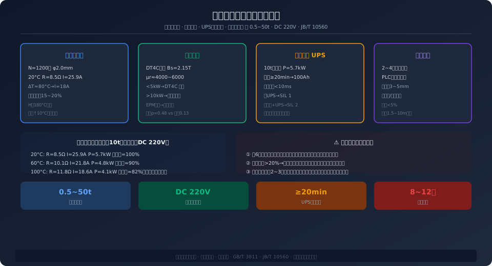
Worked coil design example: For a magnet with a Rated Lifting Capacity of 10 t, design pole-face flux density B = 1.2 T, pole area A = 4 × 200 × 150 mm = 0.12 m², theoretical holding force F = 1.2² × 0.12 / (2 × 4π × 10⁻⁷) ≈ 68.8 kN ≈ 7 t (only 70% of the rated capacity, because air-gap reluctance losses and non-uniform field distribution must be accounted for, with a Safety factor ≥ 2). Coil parameters: copper wire diameter φ2.0 mm, N = 1,200 turns, resistance R = 8.5 Ω at 20°C, DC 220 V supply, steady-state current I = 25.9 A, power P = 5.7 kW. Temperature rise ΔT ≈ 80°C (40°C ambient, 120°C coil). At this temperature, R ≈ 12.2 Ω, I ≈ 18 A, P ≈ 3.96 kW, and holding force drops by roughly 15–20% — which is why manufacturers' rated lifting capacities already include a temperature-rise derating margin.
Core Magnetic-Circuit Optimization: DT4C Pure Iron vs. Silicon Steel Laminations
The core is the structural backbone of a lifting magnet, and its material selection directly affects magnetic-circuit efficiency and heat generation.
DT4C electrical pure iron (carbon content ≤ 0.025%) is the most common core material for lifting magnets — saturation flux density Bs ≈ 2.15 T (well above NdFeB's remanence of 1.4 T), coercivity Hc ≤ 80 A/m (minimal residual magnetism after de-energizing, ideal for the "energize-to-pick-up, de-energize-to-release" operating principle), and low cost (approximately ¥8–15/kg). However, DT4C has low electrical resistivity (ρ ≈ 0.13 μΩ·m), which produces significant eddy-current losses and heating under AC or pulsating DC supply.
Silicon steel (Si content 3–4.5%) raises resistivity by adding silicon to iron (ρ ≈ 0.48 μΩ·m, roughly 3.7 times that of pure iron), substantially reducing eddy-current losses. But silicon steel has a slightly lower saturation flux density than pure iron (Bs ≈ 2.0 T), and it is harder and more difficult to machine. In high-power (>10 kW) or high-frequency switching applications (such as EPM pulse control), grain-oriented silicon steel laminations (e.g., B30P105) are typically used — individual laminations of 0.3–0.5 mm thickness are insulated from each other with varnish, reducing eddy-current losses to 1/5–1/10 of DT4C.
Engineering material selection rule of thumb: for low power (10 kW) or AC supply, silicon steel laminations reduce eddy currents; for EPM pulse operation (high-frequency magnetization cycles under 1 second), silicon steel is mandatory — otherwise eddy currents will suppress the pulse peak current and magnetization will fail.
Power-Loss Magnetism Retention: An UPS Is Not "Fit-and-Forget"
Power-loss magnetism retention is the last line of defense in a lifting magnet's safety system, and its design requirements are far more demanding than those of a standard industrial UPS — because what's at stake is not data, but the risk of multi-ton steel plates falling.
UPS battery capacity calculation: Using a 10 t lifting magnet (5.7 kW) as an example, the required retention time is ≥ 20 minutes (covering generator startup plus operator safe-handling time). Battery capacity C = P × t / (η × V_dc), where P = 5.7 kW, t = 20 min = 0.333 h, inverter efficiency η = 0.85, DC bus voltage V_dc = 220 V. C = 5,700 × 0.333 / (0.85 × 220) ≈ 10.2 Ah. A 12 V 100 Ah lead-acid battery bank (18 cells in series = 216 V) provides roughly 80% of rated usable capacity (accounting for aging margin), supporting approximately 25 minutes including safety margin.
Battery health management: Lead-acid battery capacity degrades with charge/discharge cycles and age — typical data shows 70% capacity at 3 years and 50% at 5 years. A loaded discharge test must therefore be performed every 6 months (simulate a power failure, record actual retention time, compare against the initial baseline, and replace the battery bank if degradation exceeds 20%). This is the most overlooked yet most critical maintenance item — the direct cause of the Guangdong shipyard incident described earlier was batteries that had not been replaced in 3 years.
Dual-circuit power supply: For applications requiring higher safety integrity (such as lifting over personnel), a second independent power source (diesel generator or separate transformer) is recommended in addition to the mains + UPS configuration. On mains failure, the UPS takes over seamlessly (transfer time < 10 ms), the generator starts (typically 30–60 seconds), and once the generator stabilizes, the system automatically switches to generator supply with the UPS recharging. Holding force remains uninterrupted throughout. From an IEC 61508 functional safety perspective, a single-UPS configuration achieves approximately SIL 1 (PFDavg ≈ 10⁻²–10⁻¹), while a dual-circuit + UPS redundant configuration reaches SIL 2 (PFDavg ≈ 10⁻³–10⁻²). This aligns with the differentiated Safety factor requirements for lifting spreaders in ISO 4301 (electromagnetic ≥ 2, permanent magnet ≥ 3.5) — the lower safety factor of lifting magnets must be compensated by a more redundant power supply system.
Multi-Pole Zone Control: How One Magnet Adapts to Different Steel Plate Sizes
Large lifting magnets (>5 t) typically employ a multi-pole zone design — the magnet's bottom face is divided into 2–4 independently powered zones, with PLC control switching each zone on or off to enable flexible operation across different plate sizes:
Take a 12-pole, 4-zone lifting magnet as an example: each zone contains 3 poles (coils wired in series). Zones 1+2 cover the front section (suitable for 3 m long steel plates), zones 3+4 cover the rear section (suitable for 6 m long steel plates), all zones energized simultaneously (suitable for 10 m long steel plates), or only zone 1 energized (suitable for 1.5 m short pieces). The core challenge in zone control is magnetic flux leakage between adjacent zones — if zone 1 is energized and zone 2 is de-energized, the field from zone 1 can permeate through the core into zone 2's pole faces, leaving residual magnetism on zone 2's surface (commonly called "magnetic crosstalk"), which may inadvertently pick up small foreign objects.
Engineering solution: install a 3–5 mm non-magnetic isolation layer (such as an austenitic Stainless Steel diaphragm or epoxy-filled groove) between zones to interrupt the magnetic circuit in the core between adjacent zones. The isolation layer thickness must be optimized through 2D/3D finite element simulation (e.g., ANSYS Maxwell) to ensure leakage flux stays below 5%.
Lifting Magnet Selection Parameter Quick Reference
Kelude Heavy Industry: Overhead Crane & Gantry Crane Manufacturer
Kelude Heavy Industry is a professional manufacturer of overhead cranes and gantry cranes, integrating design, manufacturing, installation, and after-sales service. We provide high-performance, high-safety, and long-lasting material handling solutions for global industrial clients.
Complete Range of Industrial Overhead Cranes
Our product line covers a wide range of material handling equipment, including single-girder overhead cranes, double-girder overhead cranes, gantry cranes, and explosion-proof cranes. Each crane is engineered to meet the specific demands of various industrial applications, ensuring reliable performance and extended service life.
| Crane Type | Typical Application | Key Features |
|---|---|---|
| Single-Girder Overhead Crane | Light to medium duty workshops, warehouses | Compact design, low headroom, cost-effective |
| Double-Girder Overhead Crane | Heavy duty production lines, steel mills, maintenance shops | High lifting capacity, high stability, precise control |
| Gantry Crane | Outdoor yards, storage areas, precast concrete plants | No building runway required, flexible movement |
| Explosion-Proof Crane | Chemical plants, oil & gas facilities, paint shops | Explosion-proof motors and electrical components |
Customized Crane Solutions for Your Specific Needs
We understand that every operation is unique. Kelude offers fully customized crane solutions, from lifting capacity and span to control systems and special features like anti-sway technology or remote operation. Our engineering team works closely with you to design a crane that perfectly fits your workflow and facility constraints.
Rigorous Quality Control and International Safety Standards
Safety and reliability are at the core of our manufacturing process. All Kelude cranes are produced in strict accordance with international standards, including ISO 4301 for crane classification and IEC 60204-32 for electrical equipment. Every crane undergoes rigorous load testing and inspection before delivery, ensuring compliance with the highest industry benchmarks.
Professional Installation and Comprehensive After-Sales Support
Beyond manufacturing, Kelude provides complete installation services and a responsive after-sales support network. Our technicians handle the entire installation process, and our global service team is available for maintenance, spare parts, and technical consultation, minimizing downtime and maximizing your productivity.
Frequently Asked Questions About Our Cranes
Q: What is the lead time for a standard overhead crane?
A: For standard models, the lead time is typically 30 to 45 days after order confirmation. Customized cranes may require a longer production schedule, which we will confirm during the quotation phase.
Q: Can you provide cranes for hazardous environments?
A: Yes, we offer a full range of explosion-proof cranes designed for hazardous areas, complying with international explosion-proof standards. Please provide your specific area classification for a tailored solution.
Q: What is your warranty policy?
A: We provide a standard 12-month warranty on all crane components, covering any manufacturing defects. Extended warranty options are also available upon request.
Q: Do you offer spare parts and after-sales service internationally?
A: Absolutely. We have a dedicated after-sales team and can ship spare parts worldwide. Our service network ensures technical support and maintenance guidance are always accessible.
| Parameter | Small | Medium | Large | Extra Large |
|---|---|---|---|---|
| Holding Force | 0.5~3t | 3~10t | 10~30t | 30~50t |
| Rated Power | 1~3kW | 3~8kW | 8~15kW | 15~25kW |
| Coil Insulation Class | FClass(155°C) | F/HClass | HClass(180°C) | HClass+Water-Cooled |
| Core Material | DT4CElectrical Pure Iron | DT4C | DT4C/Silicon Steel Sheet | Laminated Silicon Steel |
| UPSMagnetic Retention Time | 15~20min | 20~30min | 30min | 30min+Dual UPS |
| Magnetic Pole Division | 1~2Magnetic Pole Division | 2~4Magnetic Pole Division | 4~6Magnetic Pole Division | 6~8Magnetic Pole Division |
| Reference Price(Including UPS) | ¥5,000~12,000 | ¥12,000~25,000 | ¥25,000~60,000 | ¥60,000~120,000 |
Frequently Asked Questions
Q: Which is better — a lifting magnet or a permanent magnet lifter?
A: Neither is inherently "better" — it comes down to which one fits your specific application. For continuous-duty lifting across multiple steel plate thicknesses, an electromagnetic lifter (adjustable holding force, high capacity) is the right call. For intermittent work or environments with power-outage risk, a permanent magnet lifter (zero power consumption, no demagnetization during outages) is the safer bet. For automated production lines with unmanned overhead cranes, an electro-permanent magnet (EPM) combines the strengths of both — but at the highest cost. See the pillar page for a full side-by-side comparison of all three types.
Q: Do lifting magnets run hot during operation? Is that safe?
A: Yes, some heat is normal. The coil in a lifting magnet generates heat as soon as it's energized. Steady-state temperature typically runs 60–80°C above ambient — meaning 100–120°C inside a hot summer workshop. That's by design: coils are insulated to Class H (180°C), so there's ample thermal headroom. However, if coil temperature exceeds 150°C (the housing is too hot to touch), stop the unit immediately and inspect: Is the cooling air path blocked? Is the magnet being overloaded? Is there a turn-to-turn short in the coil (which causes localized overheating, insulation failure, and ultimately total unit failure)?
Q: How often should UPS batteries be replaced, and how do I test them?
A: Lead-acid batteries should be replaced every 2–3 years — even if they seem to be working fine, because internal chemical degradation is irreversible. Testing procedure: every 6 months, perform a real discharge test under load. With the crane safely unloaded or lightly loaded, manually disconnect mains power and time how long the UPS holds the magnet, then compare against the initial calibration value. If holding time has dropped by more than 20%, replace the entire battery bank — never just a few cells, as mixing old and new accelerates degradation of the new batteries. These are general guidelines; always follow the equipment manufacturer's Maintenance Manual for specifics.
—
Standards referenced: ISO 4301, JB/T 10560, IEC 61508
